(No.MA048)1-11
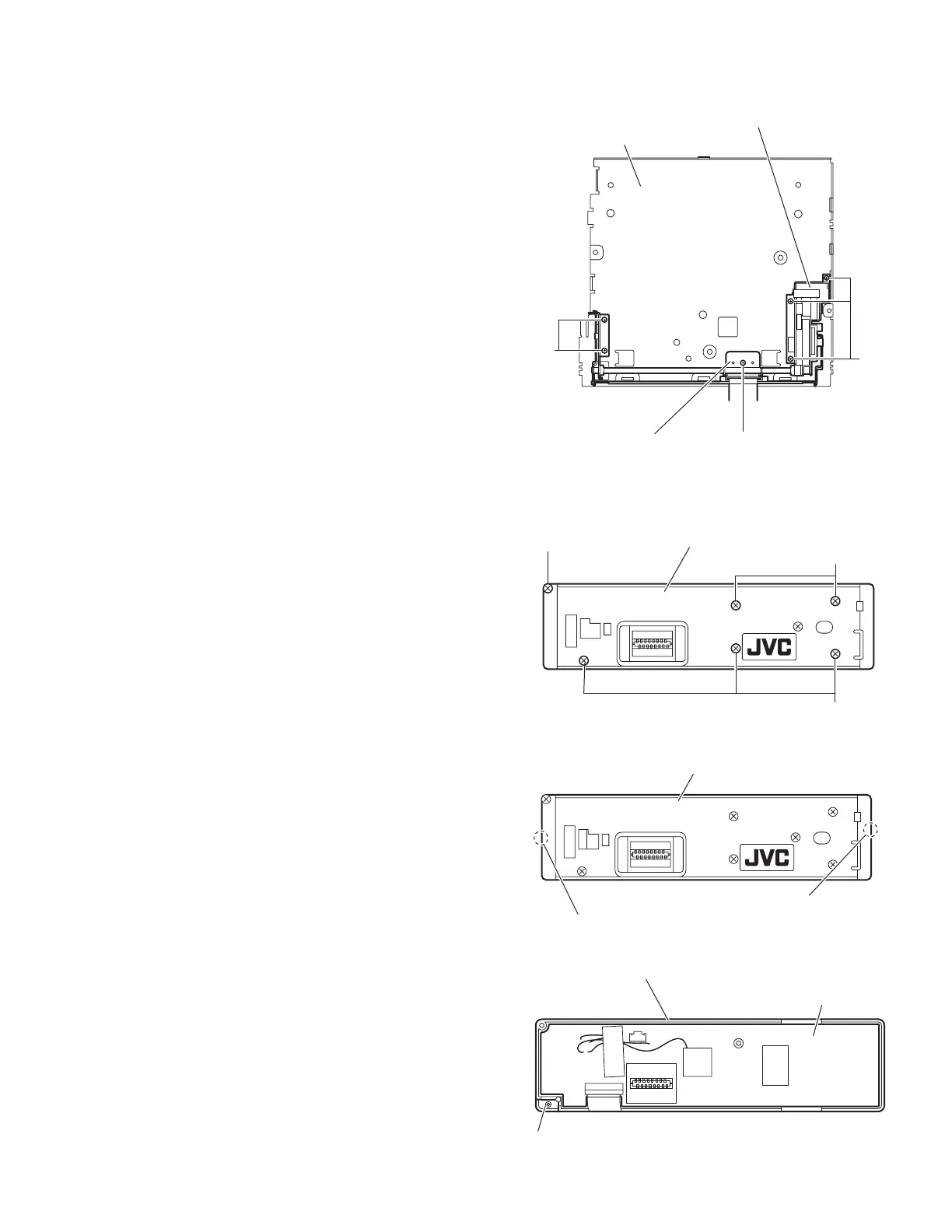
3.1.8 Removing the front door mechanism assembly
(See Fig.13)
• Prior to performing the following procedures, remove the front
panel assembly, heat sink, top chassis assembly and main
board.
(1) From the top side of the bottom chassis assembly, remove
the screw K attaching the shaft holder to the bottom chas-
sis.
(2) Remove the five screws L attaching the front door mecha-
nism assembly to the bottom chassis.
Reference:
When attaching the screws M and N, apply a locking
agent them.
(3) Take out the front door mechanism assembly from the bot-
tom chassis.
Fig.13
3.1.9 Removing the front board
(See Figs.14 to 16)
• Prior to performing the following procedures, remove the front
panel assembly.
(1) From the rear side of the front panel assembly, remove the
six screws M attaching the rear cover assembly to the front
panel assembly. (See Fig.14)
(2) Release the twelve joints a of the front panel assembly and
remove the rear cover assembly. (See Fig.15)
(3) Take out the front board from the front panel assembly.
(See Fig.16)
Caution:
Take care not to lose the spring.
Fig.14
Fig.15
Fig.16
Bottom chassis
L
L
K
Shaft holder
Front door mechanism assembly
M
Rear cover assembly
M
M
Rear cover assembly
Joints a
Joints a
Front board
Front panel assembly
Spring
 Loading...