MX-G500
1-21
(GND)
VTVM
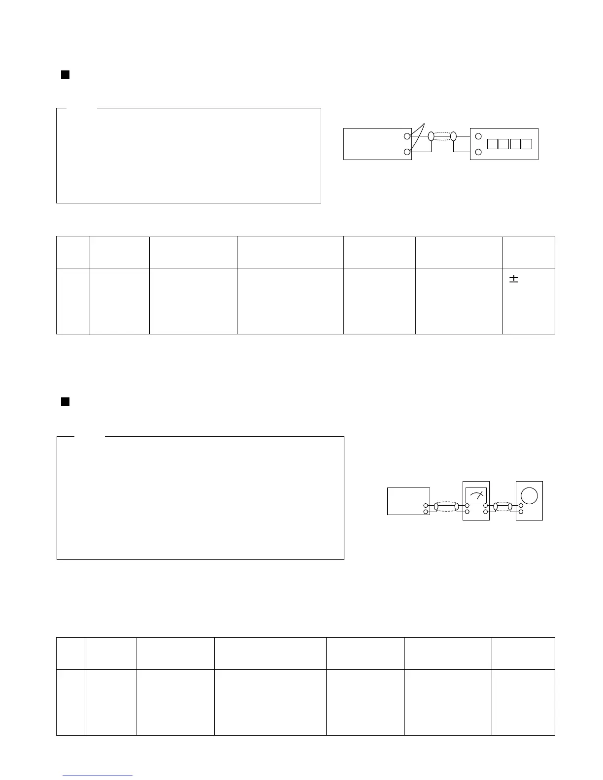
To adjust tape speed
Notes
1 3KHz
RemarkStandardPre-SetupItemStep
Pre-Setup
Condition
Cassette Deck
output
SPK OUT
Frequency Counter
Fig.1
SPK OUT
Fig.2
In Out
Cassette Deck
Oscilloscope
2. Cassette Deck
1%
range
1) Before the actual adjustment, clean the play/recording head.
2) Measuring tape :
3) The cassette deck is connections as shown in fig.2.
i) VT-703 / MTT-114N(or equivalent 10kHz AZIMUTH control)
ii) AC-225/MTT-5512(or equivalent)
Notes
AZIMUTH1 SPK OUT
(VTVM is
connected to
the scope)
To adjust plabyback level/REC
1. Adjust Deck 1 Play Level
To Adjust
RemarkStandardPre-SetupItemStep
Pre-Setup
Condition
To Adjust
1) Deck 1:VT-712
2) Press PLAY
SW button
3) Deck 2:Same
as above
OUT
(connected to the
frequencycounter)
NOR
SPEED
Control
Turn VSR1 to
left and right
(FRONT PCB)
1) Measuring tape:
i) VT-712/MTT-111(or equivalent)
(Tapes recorded with 3kHz)
ii) AC-225/MTT-5512(or equivalent)
2) Connect the cassette deck to the frequency counter
as in fig.1.
After putting
MTT-114N into Deck 1
- Press FWD PLAY
button.
Turn the control
screw to as
shownin Fig.3.
Max output
and same phase
(both channels)
After
adjustment
secure it with
REGION
LOCK.
 Loading...