Do you have a question about the JVC MX-G70 and is the answer not in the manual?
Essential safety guidelines for product operation and maintenance.
Crucial warnings regarding laser radiation hazards and product classification.
Procedures to prevent damage from static electricity during handling.
Steps for disassembling the main chassis, covers, and related boards like tuner.
Procedures for removing CD changer, servo, tray, and pick unit assemblies.
Procedures for removing power transformer, amplifier, and regulator boards.
Steps for removing front panel parts like cassette, display, and switch boards.
Guide to required instruments, conditions, and precautions for adjustments.
Instructions for cleaning, life assessment, and replacing the laser pickup.
Details on key integrated circuits, including diagrams and pin functions.
A comprehensive functional overview of the system's architecture.
Schematic diagrams illustrating the power supply circuitry.
Schematics for DC regulation and audio output stages.
Schematics covering main, tuner, and front panel sections.
Schematics for CD servo and head amplifier sections.
Layout diagram of the main printed circuit board.
Layout diagram for the regulation and amplifier boards.
Layout diagrams for the front and CD servo control boards.
Visual guide to the unit's overall assembly with part references.
Detailed parts list for the CD changer mechanism.
Detailed parts list for the cassette mechanism assembly.
Lists of electrical parts for various boards (regulator, main, front).
List of packing materials and included accessories.
| Frequency Response | 40Hz - 20kHz |
|---|---|
| Tuner Bands | AM/FM |
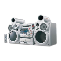
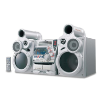
| Remote Control | Yes |
| Input Sensitivity | 500mV |
| Signal-to-Noise Ratio | 70dB |
| Connectivity | USB |
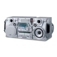
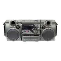
| Functions | CD Player, Radio |
| CD Changer Capacity | 1 Disc |
| Speakers | 2 |
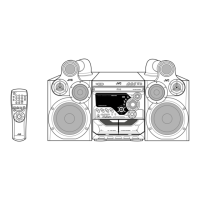
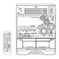
| Type | Mini System |