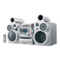
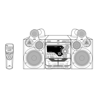
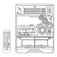
MX-G70
1-24
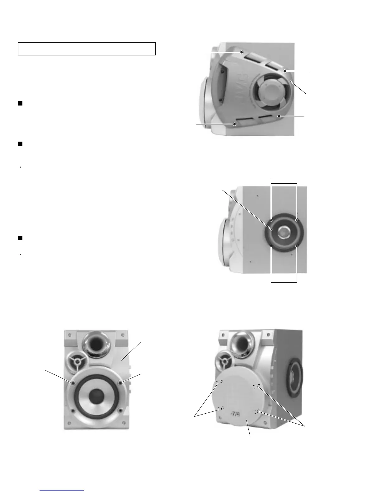
Remove the six screws A on the side of the body.1.
Removing the side cover (See Fig.1)
Prior to performing the following procedure, remove
the side cover.
Remove the four screws B on the side of the body.
Disconnect the red and black wires from the speaker
terminals on the squawker speaker.
1.
2.
Removing the squawker speaker
(See Fig.2)
Prior to performing the following procedure, remove
the side cover.
Pull out the saran net toward the front while
disengaging the four joints a.
Remove the two screw cover and two screws C
attaching the inner front cover.
1.
2.
Removing the front cover (See Fig.3 to 6)
Attention which adheres to speaker box
The speaker box of this model is a unit supply.
Therefore, we do not supply it as individual parts though
the method of disassembling the speaker box has been
described.
< Speaker section >
Fig.1
Fig.2
Fig.3
A
A
A
A
Side cover
B
Squawker speaker
Fig.4
B
Joints a
Joints a
Front cover
Screw cover
Screw cover
Saran net