MX-G71R
1-10
Prior to performing the following procedure, remove
the metal cover, the CD changer mechanism
assembly, the rear panel and the tuner board.
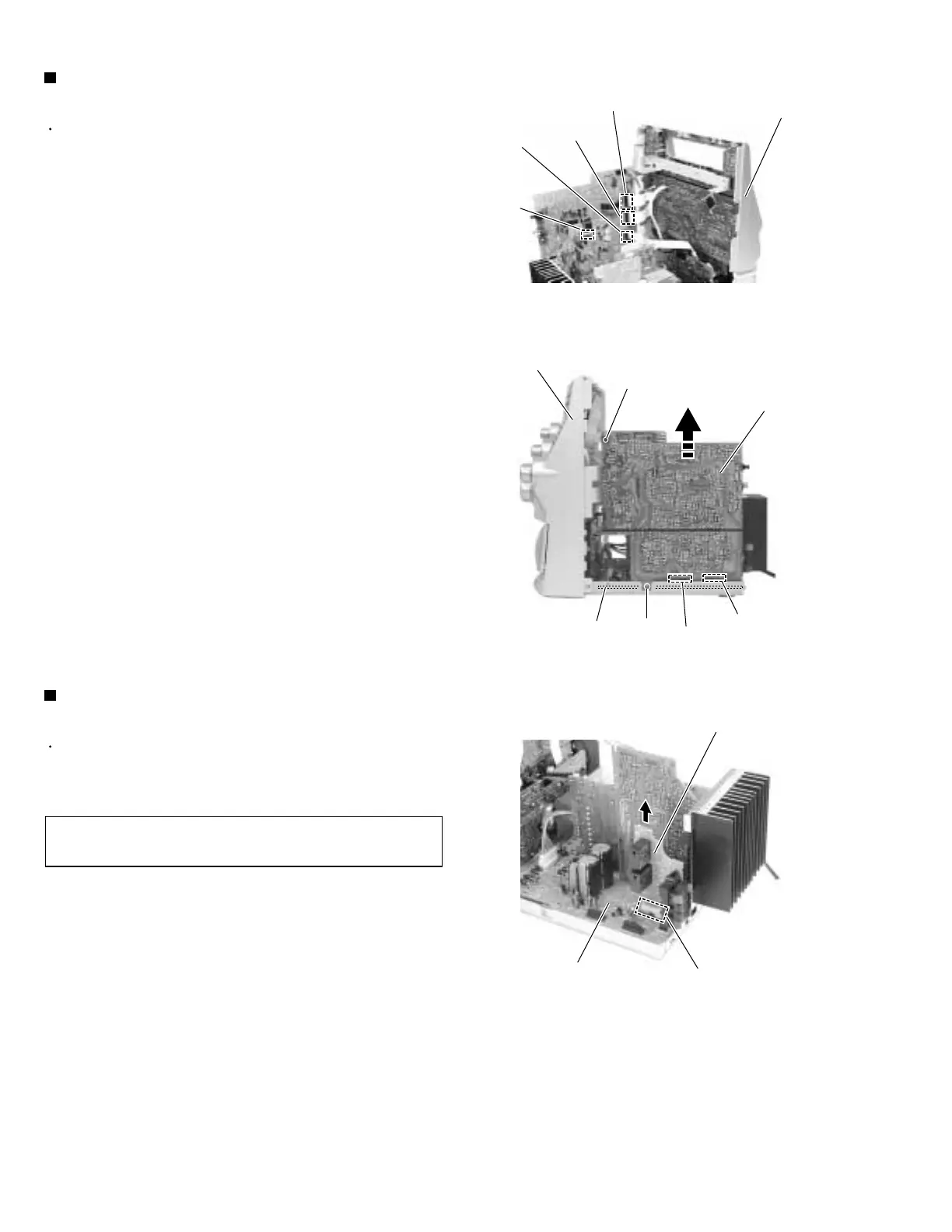
Disconnect the card wires from connector CN870,
CN871 and CN315 on the main board.
Disconnect the flat wires from connector CN704 and
CN706 on the amplifier board.
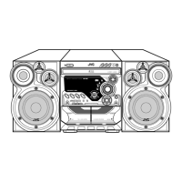
Remove the screw H attaching the main board on
the right side of the body.
Disconnect connector CN201 and CN202 on the
main board from the regulator board.
1.
2.
3.
4.
Removing the main board
(See Fig.16 and 17)
Prior to performing the following procedure, remove
the metal cover, the CD changer mechanism
assembly and the rear panel.
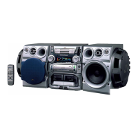
Disconnect the connector CN217 on the speaker
board from the regulator board.
1.
Removing the speaker board
(See Fig.18)
It is not necessary to remove the main
board.
REFERENCE:
Fig.16
Fig.17
Fig.18
Front panel assembly
Amplifier board
CN704
CN706
Main board
CN870
CN871
CN315
Plastic rivet
Main board
Front panel assembly
H
CN201
CN202
Regulator board
Regulator board
CN217
Speaker board