EasyManua.ls Logo

JVC MX-GA3V

JVC MX-GA3V
65 pages
To Next Page IconTo Next Page
Loading...
MX-GA3V
Contents
Safety precautions ---------------------------- 1- 2
Important for laser products ----------------- 1- 3
Preventing static electricity ----------------- 1- 4
Disassembly method ------------------------ 1- 5
Adjustment method -------------------------- 1- 18
Flow of functional
operation until TOC read -------------- 1- 20
Maintenance of laser pickup -------------- 1- 21
Replacement of laser pickup -------------- 1- 21
Description of major ICs ------------------- 1- 22
SP-MXGA3V CA-MXGA3V SP-MXGA3V
Area Suffix
US ................... SINGAPORE
UX ....................... Saudi Araia
COPYRIGHT © 2003 VICTOR COMPANY OF JAPAN, LTD.
No. MB036
2003/11
MX-GA3V
SERVICE MANUAL
COMPACT COMPONENT SYSTEM
Wiring connection ----------------------------- 1- 29
Question and Answer IconNeed help?

Do you have a question about the JVC MX-GA3V and is the answer not in the manual?

JVC MX-GA3V Specifications

General IconGeneral
BrandJVC
ModelMX-GA3V
CategoryStereo System
LanguageEnglish

Summary

Safety Precautions

Grounding and ESD Prevention

Procedures for grounding workbench and self to prevent ESD damage.

Optical Pickup Handling

Safe procedures for handling optical pickup and CD changer unit.

Laser Product Safety Information

Class 1 Laser Product Classification

Defines the product as Class 1 Laser Product and its safety implications.

Laser Radiation Exposure Warnings

Cautions regarding laser beam exposure and safety switches.

Disassembly Procedures

Top Cover and Chassis Unit Disassembly

Steps to remove the top cover and chassis components.

CD Changer Unit and Mechanism Disassembly

Steps to remove the CD changer unit and its mechanism.

Front Panel Assembly Disassembly

Steps to remove the front panel assembly.

Cassette Deck Mechanism Disassembly

Steps to remove the cassette deck mechanism.

Power Supply and Amplifier Board Removal

Steps to remove power supply and amplifier boards.

Adjustment Procedures

General Settings and Precautions

Instruments, signals, ranges, conditions, and safety notes for adjustments.

Tape Recorder Adjustments

Procedures for tape head azimuth and bias frequency alignment.

Tuner Section Adjustments

Procedures for AM tracking and IFT alignment.

Laser Pickup Maintenance and Replacement

Laser Pickup Cleaning and Lifespan

Procedures for cleaning the lens and identifying end-of-life symptoms.

Laser Power Adjustment Warning

Caution against adjusting the semi-fixed resistor for laser power.

Laser Pickup Replacement Procedure

Detailed steps for replacing the laser pickup unit.

Integrated Circuit (IC) Descriptions

Video CD Processor and Companion Chips

Pinouts and descriptions for video CD processor and companion ICs.

Audio and Control ICs

Descriptions for MIC mixer, echo mixer, REC/PCB amp, audio processor ICs.

Other Key ICs

Descriptions for shift register, VCD, CD boards, and tuner ICs.

Wiring Connection Diagram

System Interconnection Overview

Overview of component interconnections and signal flow within the system.

Block Diagram

System Interconnection Overview

Diagram showing the overall system architecture and component relationships.

Standard Schematic Diagrams

CD Servo Control Circuit

Schematic for the CD servo control circuitry.

Power, Microphone, and Headphone Circuits

Schematics for power transformer, MIC AMP, and headphone sections.

Display, CPU Control, and MPEG Circuits

Schematics for FL display, CPU control, and MPEG sections.

Audio Amplifier, Power Supply, and Tuner Circuits

Schematics for head amp, audio, power supply, and tuner sections.

Remote Control Section

Remote Control Circuit Diagram

Schematic diagram of the remote control circuitry.

Printed Circuit Board Layouts

MainPower-Amp. Board Layouts

Top and bottom side component layouts for the main/power-amp board.

CD Main Board Layouts

Top and bottom side component layouts for the CD main board.

DisplayUicom Control Board Layouts

Top and bottom side component layouts for the display/uicom control board.

MPEG Board Layouts

Top and bottom side component layouts for the MPEG board.

Tuner Board Layout

Top side component layout for the tuner board.

Parts List

General Assembly Exploded View and Parts

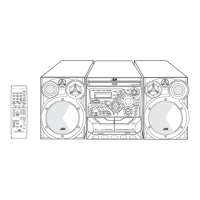
Exploded view and parts list for the main unit assembly.

CD Changer Mechanism Parts

Exploded view and parts list for the CD changer mechanism assembly.

Cassette Mechanism Parts

Exploded view and parts list for the cassette mechanism assembly.

Electrical Components List

Detailed list of electrical parts for the main board.

Packing and Accessories List

List of packing materials and included accessories.
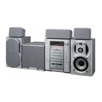
Related product manuals