MX-GA3V
1-17
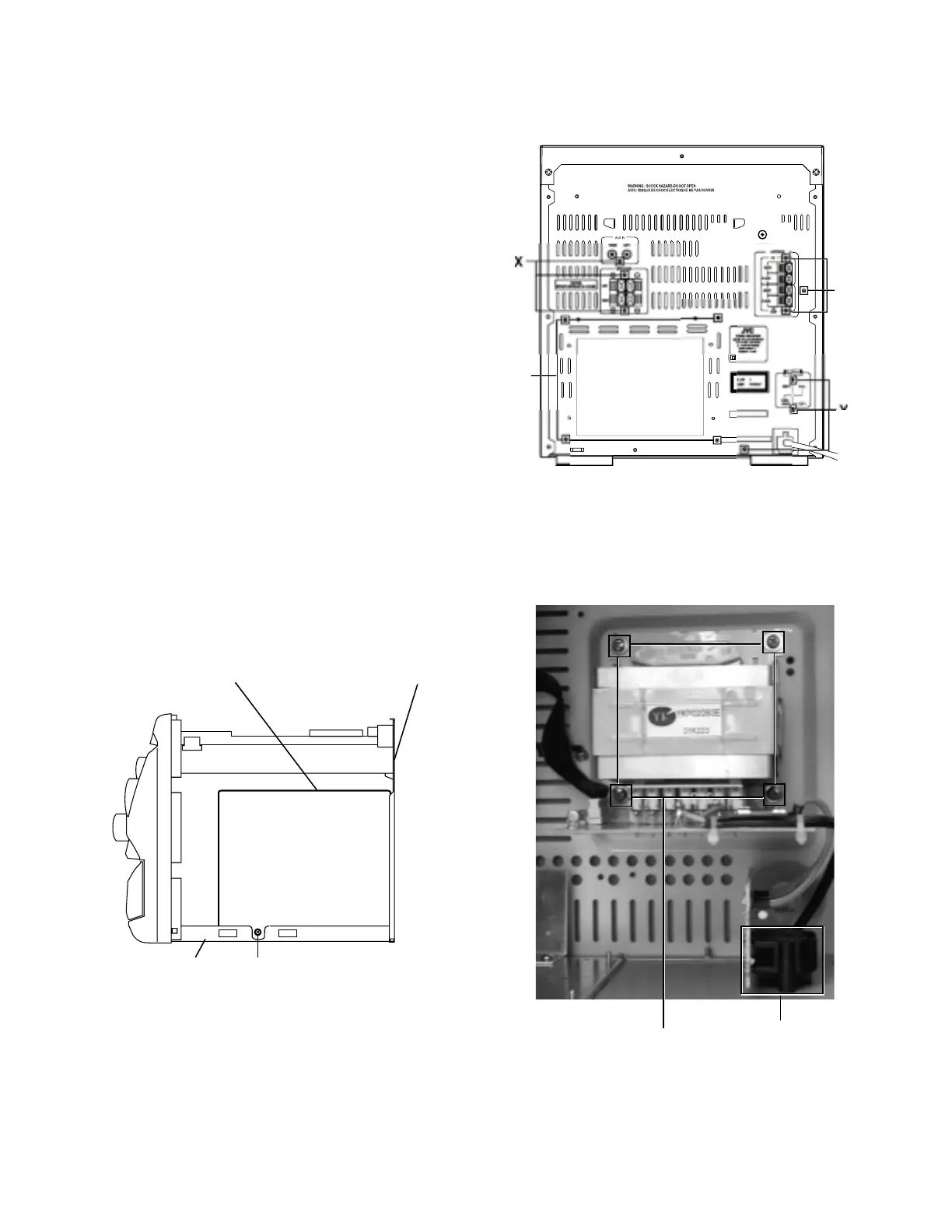
Rear panel
Chassis
Z
Power AMP and
supply PCB
Removing the power amp and supply PCB
and the power trans PCB
(See Fig. 2, 29 to 31)
Prior to performing the following procedures, remove
the top cover and CD changer unit.
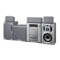
1. Remove four screws
B
from the rear panel. (Fig.3)
2. Pull the heat sink cover outward.
3. Remove
four screws
AA
from the rear panel between
the heat sink holder.
4. Remove two screws
X
that retain the speaker terminals
and AUX terminal.
5. Remove screws
YY
that retains the rear panel, and
then remove the rear panel.
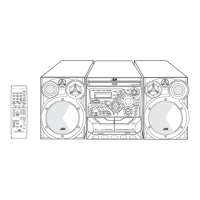
6. Disconnect the parallel wires from the connectors
FW951 on the power trans PCB.
7. Remove the clamp of AC power cord from the chassis.
8. Remove four screws
AB
that retain the power trans
PCB and then remove the assembly.
Fig.33
Fig.34
AB
AC Selector
Switch
Fig.34