MX-GA3V
1-16
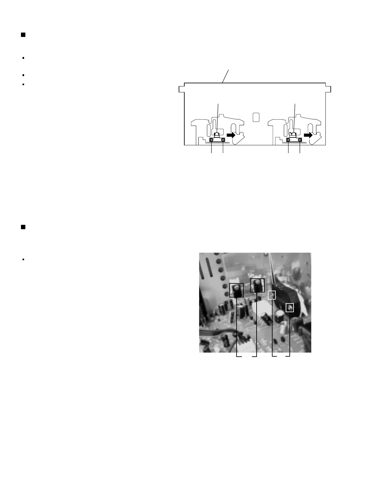
Fig.30
Cassette deck mechanism
(Front side)
V
U
PB Head REC/PB Head
Removing the cassette deck heads
(See Fig. 21 and 30)
Prior to performing the following procedures, remove
the top cover and both sides board.
Also remove the CD changer unit.
Also remove the front panel assembly.
1. Remove five screws Z that retain the cassette deck
mechanism. (Fig.21)
2. Remove the cassette deck mechanism and place
it so that the front side faces up.
3. Remove the solder from the bottom side of the head
terminal and disconnect the wire.
4. Remove screw U that retains the head.
5. Remove screw V that retains the head.
6. Hold the head and slide it in the direction of the
arrow to remove it.
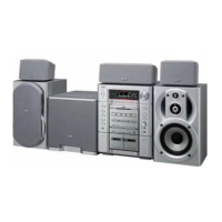
Removing the 3-pin regulator and bridge
diode
(See Q904, Q907 and Fig.31)
Prior to performing the following procedures, remove
the top cover and both sides board.
1. Remove two screws A that connect the heat sink
cover to rear panel.
2. Pull the heat sink outward.
3. Remove two screws W that retains the heat sink the
3-pin terminal regulator Q904, Q907.
4. Remove the solder fixing the 3-pin regulator.
V
U
W
Fig.31
A