MX-GA3V
1-13
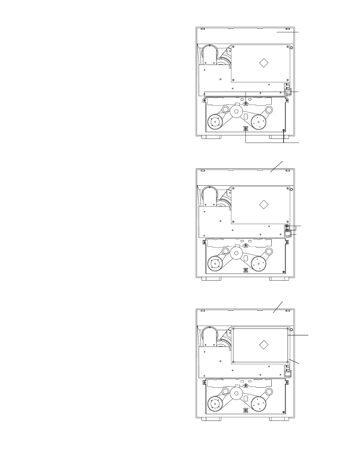
Fig.21
Z
Z
Front panel
assembly
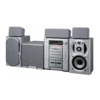
Fig.22
P
Front panel
assembly
Earphone jack
PCB
Front panel
assembly
Q
Control/FL
PCB
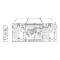
Fig.23
Removing the cassette deck mechanism
(See Fig.21)
Prior to performing the following procedures, remove
the top cover.
Also remove the CD changer unit.
Also remove the front panel assembly.
1. Remove five screws
Z
retaining the cassette deck
mechanism.
Removing the earphone jack PCB and
Mic Jack PCB
(See Fig.22)
Prior to performing the following procedures, remove
the top cover and both sides board.
Also remove the CD changer unit.
Also remove the front panel assembly.
1. Remove the screw with the washer,
P
that
retains the earphone jack PCB.
Removing the control/FL PCB
(See Fig.21)
Prior to performing the following procedures, remove
the top cover and both sides board. Also remove
the CD changer unit.
Also remove the CD changer unit.
Also remove the front panel assembly.
1. Remove four screws
Q
that retain the control/FL PCB
from the back of the front panel unit.