MX-GA3V
1-14
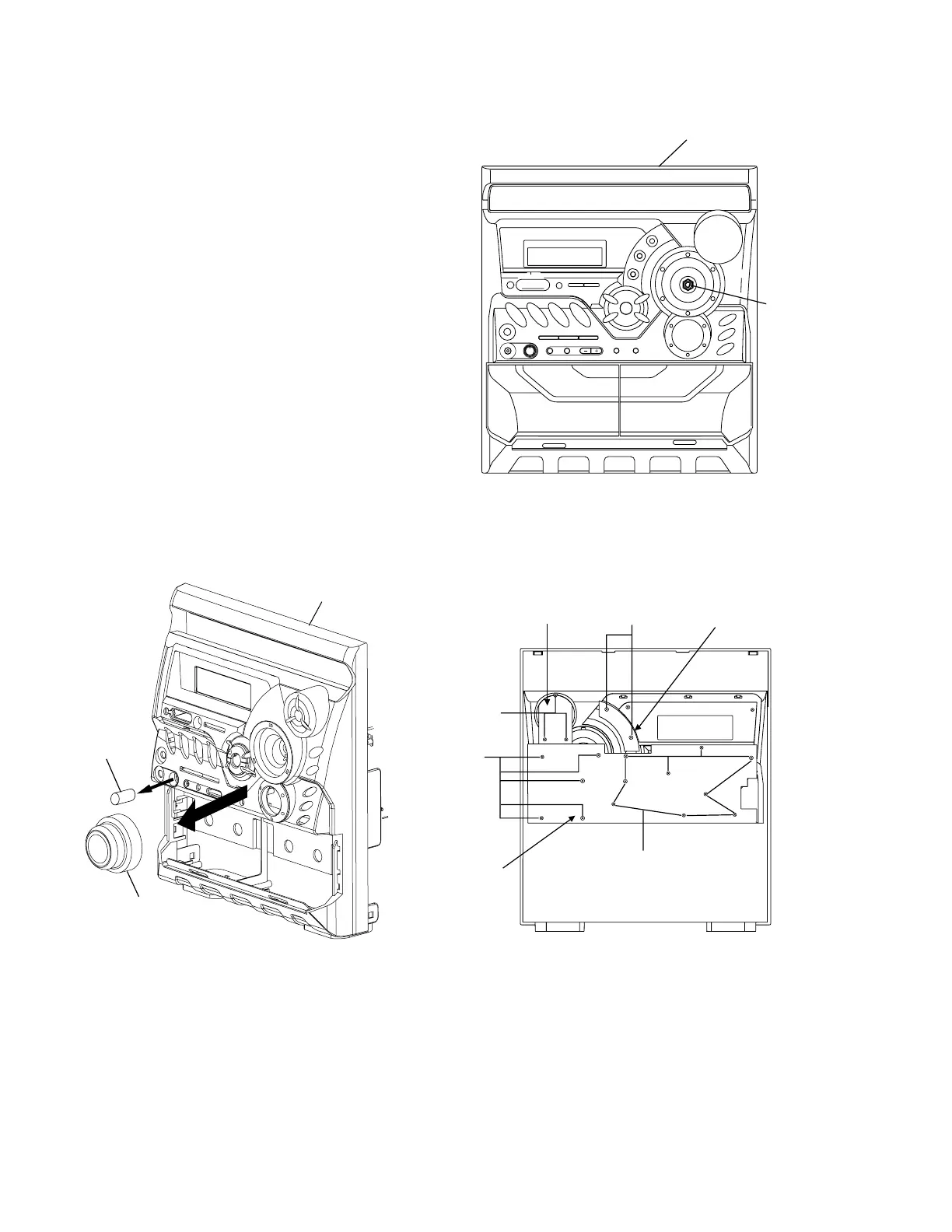
Fig.25
Front panel
assembly
Volume
shaft
Fig.26
Key 1 PCB
R
S
T
R
Key 2 PCB
Key 3 PCB
Removing the switch PCB and sound
mode and CD function switch PCB
(See Fig.23 to 26)
Prior to performing the following procedures, remove
the top cover and both sides board.
Also remove the CD changer unit.
Also remove the front panel assembly.
1. Pull out the volume control knob and MIC Volume
Knob from the front of the front panel assembly.
(Fig.24)
2. Remove four screws
Q
retaining the front panel
assembly. (Fig.23)
3. Remove the control/FL PCB.
4. Remove eleven screws
R
retaining the switch (key 1)
PCB. (Fig.22)
5. Remove three screws
S
retaining the sound mode
(key 2) switch PCB.
6. Remove two screws
T
retaining the CD function
(key 3) switch PCB.
Fig.24
Volume Knob
Front panel assembly
MIC Volume
Knob