MX-GA3V
1-9
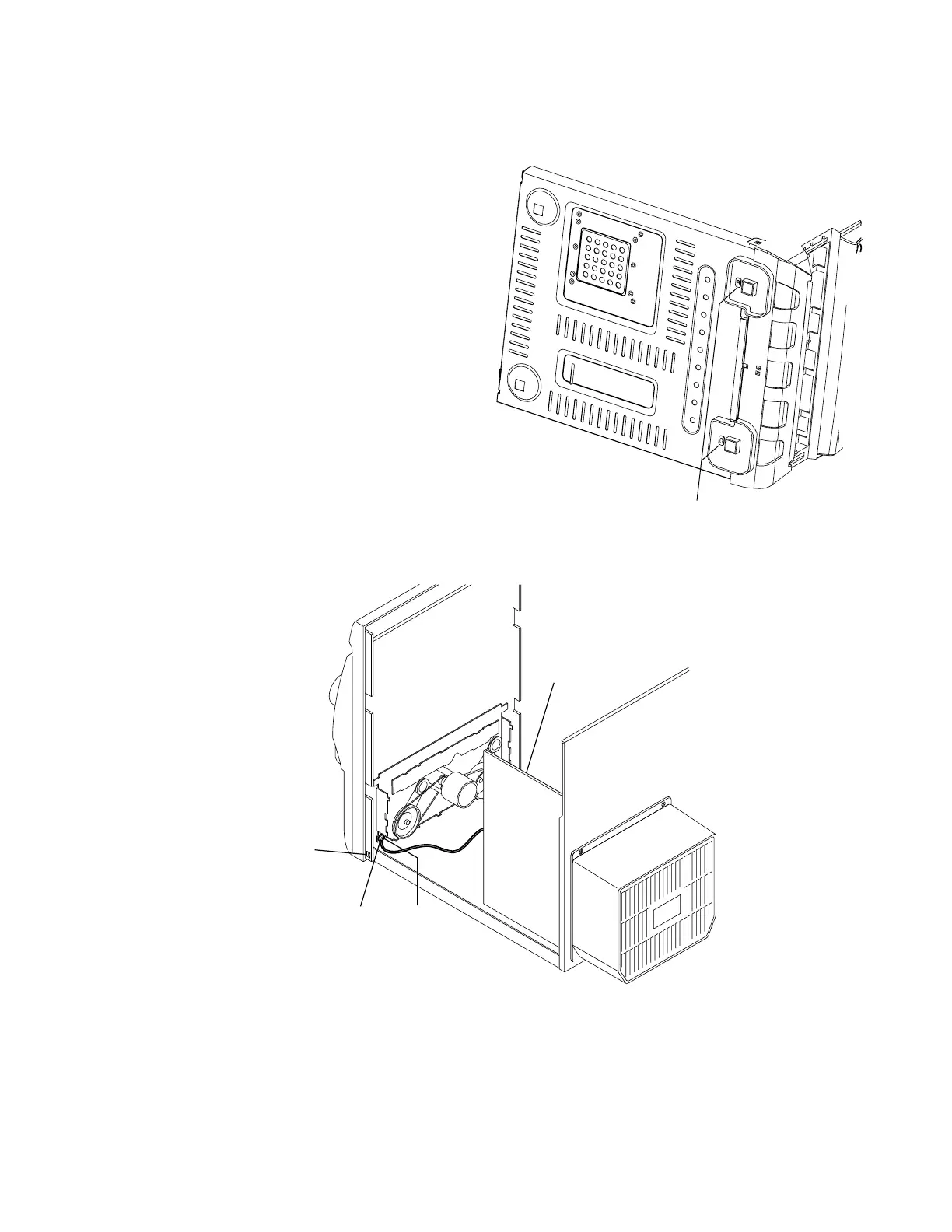
Fig.10
H
Fig.12
I
Power amp and
supply PCB
Claw
c
GND lug
b
Removing the front panel assembly
(See Fig.10 to 11)
Prior to performing the following procedures, remove
the top cover and both board.
Also remove the CD changer unit.
1. Disconnect the parallel wire and the cord wire from
the connectors CN701, CN702, CN703, CN850 on
the power amp. and supply PCB.
2. Remove two screws
H
retaining the front panel
assembly onto the bottom of the body.
3. Remove two screws I on the left and right side of the set
retaining the panel front from the bottom and then
remove then GND lug
b
that comes from the power
amp and supply PCB.
4. Disengage the claws
c
on both sides of the front
panel assembly and then remove the assembly.