MX-GA3V
1-10
Fig.14
CD PCB
Short round
CN601
<Disassembly of units and assembly
inside this set>
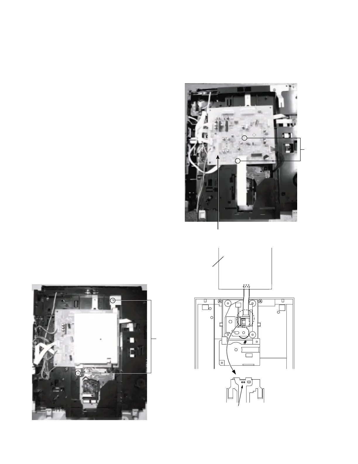
Removing the CD PCB
(See Fig.12 to 13)
Prior to performing the following procedures, remove
the top cover and both sides board.
Also remove the CD changer unit.
1. The two screws
E
that retain the VCD assembly
should be removed.
2. Disconnect the wires from CN602, CN603, CN604
and CN605 on the CD PCB, which is located on
the back side of the CD changer unit.
3. The two screws
J
that retain the CD PCB should be
removed.
4. Remove the CD PCB by pulling it toward the side
where the CN601 is located.
5.
Using solder, short the CD pickup to connect to
short round.
[Caution]
After re-connecting the wires, be sure to
remove the shorting solder from the GND
connection.
6. Disconnect the card wire from the connector CN601
on the main PCB and then remove the main PCB.
Fig.12(A)
E
Fig.12(B)
J
CD PCB