Do you have a question about the JVC MX-KA5 and is the answer not in the manual?
Detailed schematic for the main operational circuits of the system.
Schematic diagram for the radio tuner subsystem.
Schematic diagram for the compact disc playback subsystem.
Schematic diagram for the audio amplification circuitry.
Schematic for the front panel display and control interface.
Schematic for the power transformer and related circuitry.
Top layer layout of the main circuit board, showing component placement.
Bottom layer layout of the main circuit board, showing traces and connections.
Top layer layout of the front panel control and display circuit board.
Bottom layer layout of the front panel control and display circuit board.
Component layout for the amplifier circuit board.
Component layout for the power transformer circuit board.
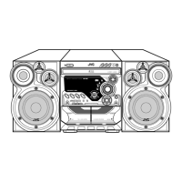
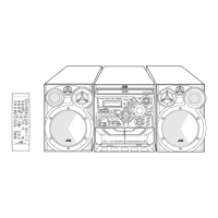
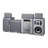
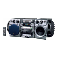
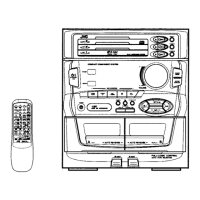
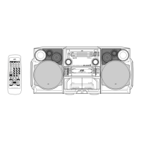
| Brand | JVC |
|---|---|
| Model | MX-KA5 |
| Category | Stereo System |
| Language | English |