EasyManua.ls Logo

JVC MX-KB2 - User Manual

JVC MX-KB2
73 pages
To Next Page IconTo Next Page
Loading...
SERVICE MANUAL
COPYRIGHT © 2004 Victor Company of Japan, Limited
No.MB284
2004/8
COMPACT COMPONENT SYSTEM
MB28420048
MX-KB2,MX-KB1
TABLE OF CONTENTS
1 PRECAUTION. . . . . . . . . . . . . . . . . . . . . . . . . . . . . . . . . . . . . . . . . . . . . . . . . . . . . . . . . . . . . . . . . . . . . . . . . 1-3
2 SPECIFIC SERVICE INSTRUCTIONS . . . . . . . . . . . . . . . . . . . . . . . . . . . . . . . . . . . . . . . . . . . . . . . . . . . . . . 1-6
3 DISASSEMBLY . . . . . . . . . . . . . . . . . . . . . . . . . . . . . . . . . . . . . . . . . . . . . . . . . . . . . . . . . . . . . . . . . . . . . . . 1-7
4 ADJUSTMENT . . . . . . . . . . . . . . . . . . . . . . . . . . . . . . . . . . . . . . . . . . . . . . . . . . . . . . . . . . . . . . . . . . . . . . . 1-27
5 TROUBLESHOOTING . . . . . . . . . . . . . . . . . . . . . . . . . . . . . . . . . . . . . . . . . . . . . . . . . . . . . . . . . . . . . . . . . 1-31
Area suffix
UW ----------- Brazil,Mexico,Peru

Other manuals for JVC MX-KB2

Question and Answer IconNeed help?

Do you have a question about the JVC MX-KB2 and is the answer not in the manual?

JVC MX-KB2 Specifications

General IconGeneral
BrandJVC
ModelMX-KB2
CategoryStereo System
LanguageEnglish

Summary

SPECIFICATIONS

SECTION 1 PRECAUTION

General Safety Guidelines

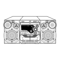
Covers general safety rules, warnings, cautions, and critical component identification.

Static Electricity and Traverse Unit Handling

Procedures for preventing static damage and handling the optical pickup traverse unit.

Laser Product Safety Information

Important information and warnings related to laser product operation and safety.

SECTION 2 SPECIFIC SERVICE INSTRUCTIONS

SECTION 3 DISASSEMBLY

Main Unit and CD Mechanism Disassembly

Steps to remove the main body, covers, CD fitting, and CD changer mechanism.

Board and Panel Removal

Procedures for removing tuner, speaker terminal, front panel, switch, LCD, system, and cassette boards.

Power Supply and Main Board Removal

Steps for removing rear panel, heat sink, power board, transformer, and main board.

Speaker Component Removal

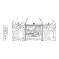
Instructions for removing the speaker front cabinet and speaker units.

SECTION 4 ADJUSTMENT

Measurement Setup and Conditions

Required instruments and specific measurement conditions for various sections.

Cassette and Tuner Adjustments

Detailed steps for adjusting cassette amp and tuner sections.

Operational Flow and Part Locations

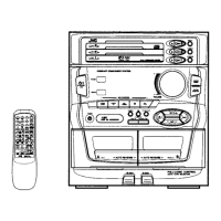
Guide to functional operations and locations of adjustment parts.

SECTION 5 TROUBLESHOOTING

SCHEMATIC DIAGRAMS

Wiring and Block Diagrams

Visual representation of wiring and functional blocks of the system.

Detailed Schematic Sections

Schematics for power amp, protection circuits, and other key functional areas.

Printed Circuit Board Layouts

Visual layouts of the main, display, tuner, and power circuit boards.

PARTS LIST

Exploded Assembly and Parts Identification

Visual breakdown of assemblies with numbered parts for easy identification.

Electrical Component Listings

Comprehensive lists of electrical parts for main, power, display, and tuner boards.

Packing and Accessories

List and illustration of packing materials and included accessories.

Related product manuals