Do you have a question about the JVC MX-D401T and is the answer not in the manual?
Essential safety guidelines for operation and maintenance.
Critical safety information for laser components and handling procedures.
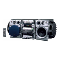
Initial setup, accessories, and remote control usage.
Explains basic functions like volume control, sound modes, and power.
Instructions for playing CDs, including track selection and playback modes.
Operations for listening to tapes, including playback and lock functions.
Steps for recording from various sources to CD, including pausing and stopping.
Guidelines for maintaining the unit, including care for CDs and general notes.
Diagrams showing the placement of major internal components.
Steps for removing the external metal cover and CD traverse mechanism.
Procedures for removing the front panel and cassette mechanism assemblies.
Steps for removing the rear panel and main amplifier board.
Lists the necessary instruments and conditions for performing adjustments.
Procedures and standard values for checking tape playback and recording performance.
Detailed pin configurations and functional descriptions for main ICs.
Overall wiring schematic showing connections between major boards.
Exploded diagram of the unit's enclosure with numbered parts.
List of parts for the cassette mechanism assembly.
High-level overview of the system's functional blocks and signal flow.
Detailed schematic of the head amplifier and control circuitry.
Schematic diagram of the tuner section.
Schematic for amplifier, bass boost, and regulator circuits.
Schematic for the system CPU and operation switch board.
Diagram showing component placement on the main amplifier board.
Diagram illustrating component placement on the power supply and amplifier board.
Comprehensive list of electrical components for the main amplifier board.
Comprehensive list of electrical components for the power supply/amplifier board.
Visual guide for packing the unit for shipping or storage.
Lists of items included in packing and available accessories.
| Brand | JVC |
|---|---|
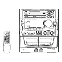
| Model | MX-D401T |
| Category | Stereo System |
| Language | English |