(No.MB284)1-7
SECTION 3
DISASSEMBLY
3.1 Main body
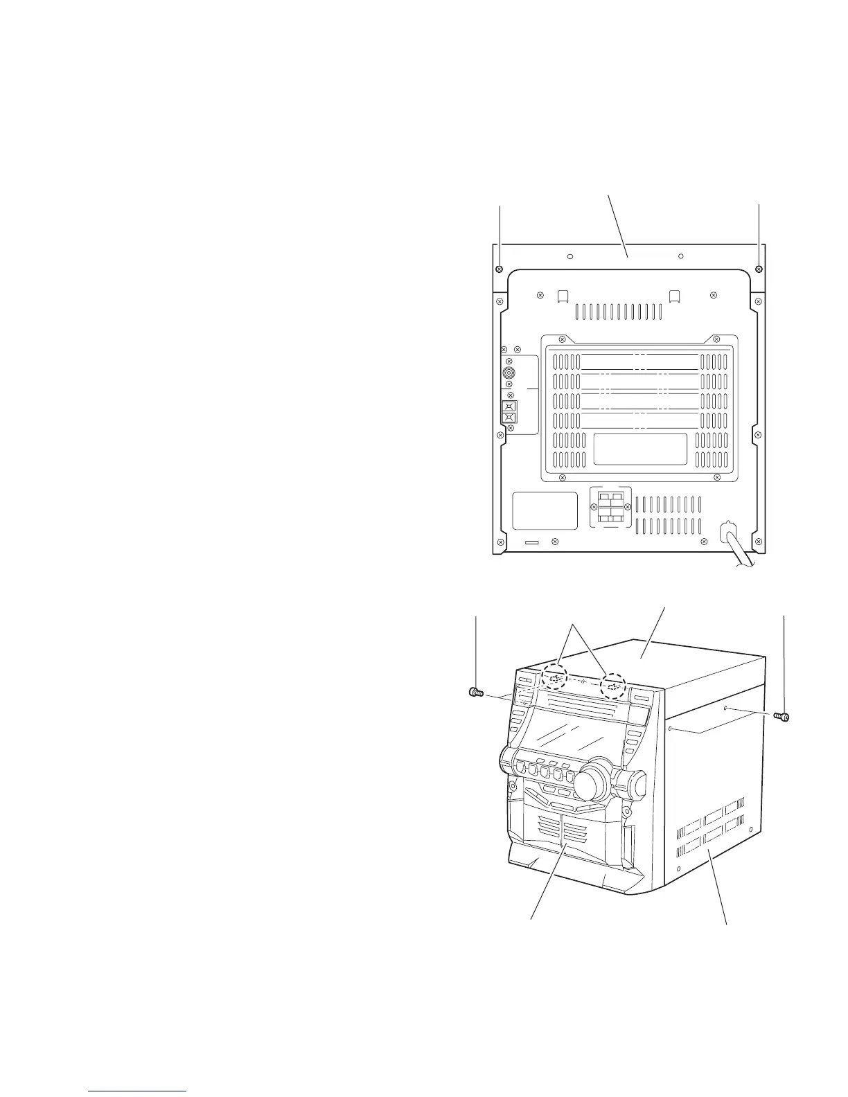
3.1.1 Removing the top cover / side cover (R) and (L)
(See Fig.1 to 6)
(1) From the back of the body, remove the two screws A at-
taching the top cover.
(2) From both sides of the body, remove the four screws B at-
taching the top cover and the side cover (R) and (L). Move
the top cover in the direction of the arrow to release from
the front panel at the two joints a.
(3) Remove the six screws D on the back of the body and the
two screws E on the side of the body. Move the side cover
(R) and (L) backward to release the four joints b on the bot-
tom of the side covers.
Fig.1
Fig.2
A
A
Top cover
Top cover
Front panel assembly
Side cover (R)
B
a
B