MX-GT90
1-7
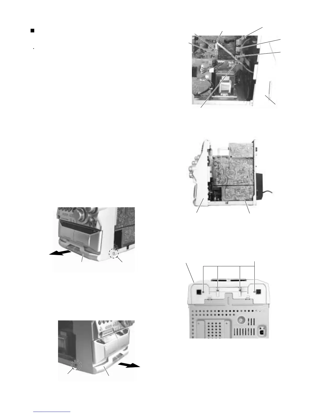
Remove the four screws E on the bottom of the
body.
Release the two joints a on the lower right and left
sides of the body using a screwdriver, and remove
the front panel assembly toward the front.
4.
5.
Prior to performing the following procedure, remove
the metal cover and CD changer mechanism
assembly.
Disconnect the card wires from connector CN870,
CN871 and CN315 on the main board respectively.
Remove the tie band and disconnect the wire from
connector CN703 on the amplifier board.
Disconnect the wire from connector CN220 on the
transformer board.
1.
2.
3.
Removing the front panel assembly
(See Fig.6 to 10)
Fig.8
Fig.9
Fig.10
E
(Bottom)
Front panel assembly
Joint a
Joint a
Front panel assembly
Front panel assembly
Fig.7
Front panel assembly
Main board
Fig.6
Tie band
Amplifier board
CN703
Main board
CN870
CN871
CN315
Transformer board
CN220
Front panel
assembly
CN705
 Loading...