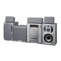
MX-J570V/MX-J680V
1-10
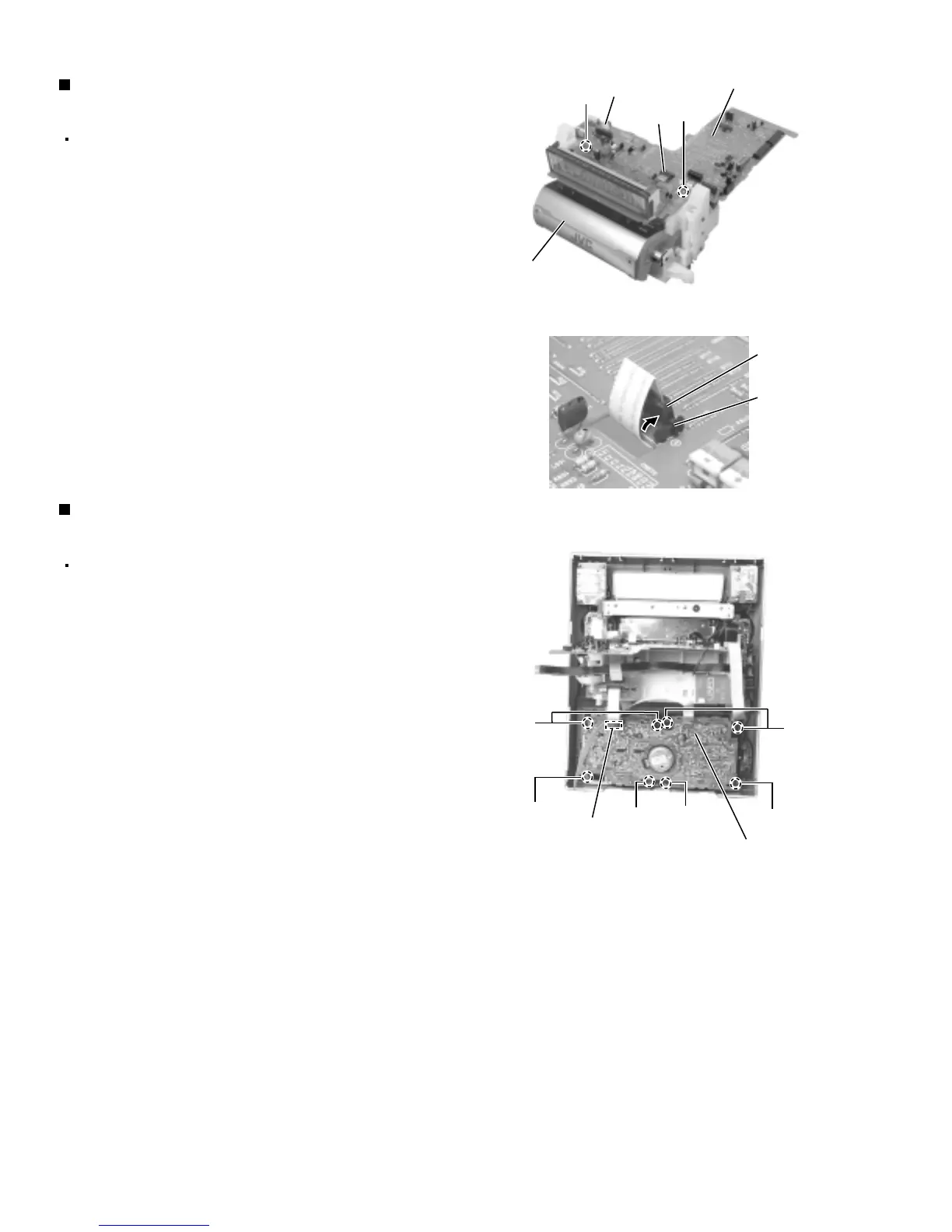
Prior to performing the following procedure, remove
the front panel assembly, the microphone terminal
board and the rolling panel assembly.
Disconnect the harness from connector CN867 on
the main board.
Disconnect the card wire from connector CN879 on
the main board (Before pulling out the card wire,
stand the part d of CN879 as shown in Fig.15).
Remove the two screws N attaching the main board.
1.
2.
3.
Removing the main board
(See Fig.14 and 15)
Prior to performing the following procedure, remove
the front panel assembly.
Disconnect the card wire from connector CN306 on
the cassette mechanism board.
Remove the eight screws O and P attaching the
cassette mechanism assembly.
Pull out the cassette mechanism assembly toward
you.
1.
2.
3.
Removing the cassette mechanism
assembly (See Fig.16)
Fig.14
Fig.15
Fig.16
Main board
N
Rolling panel
assembly
N
CN867
CN879
CN879
d
Cassette mechanism board
O
P
P
O
P
P
CN306
 Loading...