1-18 (No.MB282)
3.1.14 Removing the FL board
(See Figs.23 and 24)
• Prior to performing the following procedures, remove the metal
cover and front panel assembly.
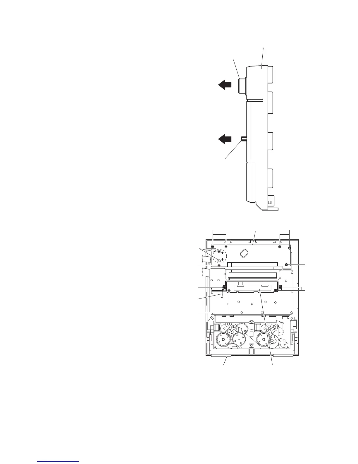
(1) From the front side of the front panel assembly, pull the vol-
ume knob out of the front panel assembly. (See Fig.23.)
(2) From the inside of the front panel assembly, remove the six
screws W attaching the FL board. (See Fig.24.)
(3) Release the claws q in the direction of the arrow and take
out the FL board from the front panel assembly. (See
Fig.24.)
3.1.15 Removing the switch board
(See Figs.23 to 25)
• Prior to performing the following procedures, remove the metal
cover and front panel assembly.
(1) From the front side of the front panel assembly, pull the mi-
crophone knob out of the front panel assembly. (See
Fig.23.) [US/UX/UN version only]
(2) From the inside of the front panel assembly, remove the
three screws X and screw X’ attaching the stay bracket.
(See Fig.24.)
Reference:
When attaching the screw X’, attach the earth wire with
it.
(3) Remove the ten screws Y and screw Y’ attaching the
switch board. (See Fig.25.)
Reference:
When attaching the screw Y’, attach the wire holder with
it.
(4) Take out the switch board from the front panel assembly.
Fig.23
Fig.24
Microphone knob
Volume knob
Front panel assembly
WW
W
X
W
FL board
q
Stay bracketFront panel assembly
X
X'
Earth
wire