1-18
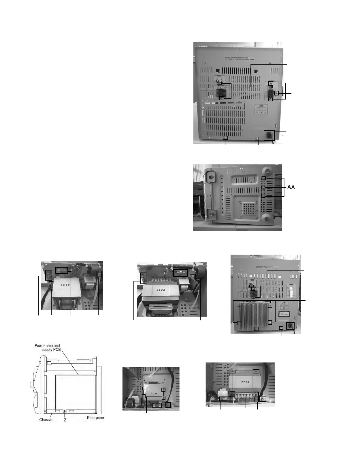
n Removing the power amp and supply
PCB and the power trans PCB
(See Fig. 2, 3, 32, 34 to 37)
n
Prior to performing the following procedures, remove
the top cover and both sides board.
n
Also remove heat sink cover.(Fig.4)
1. Remove the two screws "A" connecting the heat sink
cover to the rear panel.(Fig.2, 3)
2. Pull out the heat sink cover toward you.
3. Remove the three (CA-MXK10/K15R)/ four(CA-MXK30)
screws "AA" form the (CA-MXK10/K15R) chassis /
MX-K30 back panel between the heat sink.
4. Remove the three screws "X" that retain the speaker
terminals and AUX terminal.
5. Remove the screw "YY" that retains the rear panel,
and then remove the rear panel.
6. Disconnect the parallel wires from the connectors
FW951 and CN981 on the power trans PCB.
7. Remove the screw "Z" that retain the power amp and
supply PCB and then remove the assembly.
8. Remove the clamp of AC power cord from the chassis.
9. Remove the four screws "AB" that retain the power
trans PCB and then remove the assembly.
YY
BB
X
CLAMP
For CA-MXK10R/K15R Fig.34(A)
For CA-MXK30R Fig.37(B)
Fuse F981
T2AL 250V
AB
FW 951
Fuse F952
T1.6AL 250V
AB
For CA-MXK10R/K15R Fig.37 (A)
X
Y
YY
CLAMP
For CA-MXK30R Fig.34(B)
Fuse(F952)
T1.6AL 250V
Fuse (F981)
T2AL 250V
CN981
For CA-MXK30R Fig.35(B)
Component SIDE
Fuse (F952)
T1.6AL 250V
FW981
Fuse(F981)
T1AL 250V
CN981
For CA-MXK10R/K15R Fig.35 (A)
Component SIDE
Fig.36
For CA-MXK10R/K15R Fig.34(A)