(No.MB196)1-7
SECTION 3
DISASSEMBLY
3.1 Disassembly of the main blocks of the set
Replacement of the fuses and the power IC
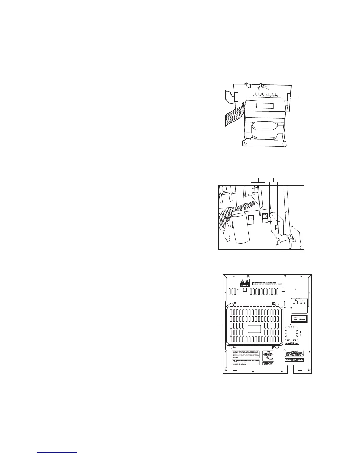
3.1.1 Replacing the fuses
(See Fig.1)
• Prior to performing the following procedure, remove the left
side board.
(1) Replace the fuses inside.
Caution:
Be sure to use fuses with the specified ratings.
Fig.1
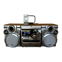
3.1.2 Replacing the power IC
(See Fig.2)
• Prior to performing the following procedure, remove the top
cover.
(1) Remove the two screws A from the heat sink between the
power IC.
(2) Remove the solder fixing the power IC.
Fig.2
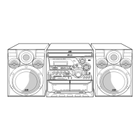
3.1.3 Replacing the heat sink cover
(See Fig.3)
(1) Remove four screws B from the rear panel.
(2) Pull the heat sink cover outward.
Fig.3
Fuse (F901)
3.5A 125V
Fuse (F902)
1.6A 250V
W
A
B