PD-42DX
(No.52088)1-9
2.4 DISASSEMBLY PROCEDURE [DISPLAY UNIT]
Caution:
• When exchanging parts etc. with the front side (PDP side)
facing down, please place a protection sheet below before
starting, so as to prevent scratches on the front side.
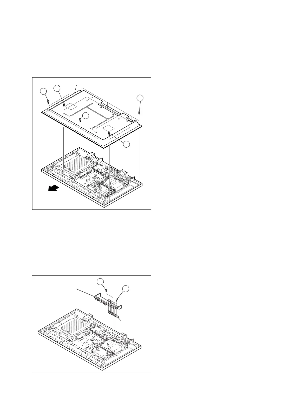
2.4.1 REMOVING THE REAR COVER (Fig.1)
(1) Remove the power cord / system cable / speaker cord.
(2) Remove the 19 screws [A] and the 6 screws [B], and
remove the REAR COVER.
Fig.1
2.4.2 REMOVING THE TERMINAL COVER (Fig.2)
• Remove the REAR COVER.
(1) Remove the 2 screws [C], and withdraw the TERMINAL
COVER.
(2) Remove the 6 screws [D], and remove the SPEAKER
TERMINAL PWB.
NOTE:
• Disconnect the connector [CN60SP] from the
SPEAKER TERMINAL PWB.
Fig.2
2.4.3 REMOVING THE LINE FILTER PWB (Fig.3)
• Remove the REAR COVER.
• Remove the TERMINAL COVER.
(1) Remove the 6 screws [E], and remove the LINE FILTER
PWB together with the filter shield.
NOTE:
• Disconnect the connector [CN0PW] from the LINE
FILTER PWB.
• Disconnect the connector [CN900P] from the
SYSTEM POWER PWB.
• It is advisable to take note of the connecting location
(connector number) of the removed connectors.
2.4.4 REMOVING THE AUDIO PWB (Fig.3)
• Remove the REAR COVER.
• Remove the TERMINAL COVER.
(1) Remove the 4 screws [F], and remove the AUDIO PWB.
NOTE:
• Disconnect the connectors [CN60SP], [CN600K],
[CN60CA], [CN60CE], [CN60CF] from the AUDIO
PWB.
• It is advisable to take note of the connecting location
(connector number) of the removed connectors.
2.4.5 REMOVING THE SYSTEM POWER PWB (Fig.3)
• Remove the REAR COVER.
• Remove the TERMINAL COVER.
(1) Remove the 4 screws [G], and remove the SYSTEM
POWER PWB.
NOTE:
• Disconnect the connectors [CN900J], [CN90CB],
[CN90CA], [CN900K] from the SYSTEM POWER
PWB.
• It is advisable to take note of the connecting location
(connector number) of the removed connectors.
2.4.6 REMOVING THE DISPLAY INTERFACE PWB (Fig.3)
• Remove the REAR COVER.
• Remove the TERMINAL COVER.
(1) Remove the 2 screws [H], and remove the DISPLAY
INTERFACE PWB.
NOTE:
• Disconnect the connectors [CN0AH], [CN0CB],
[CN0CD], [CN0CC], [CN0AV], [CN0CF], [CN0CE]
from the Monitor Interface PWB.
• It is advisable to take note of the connecting location
(connector number) of the removed connectors.
2.4.7 REMOVING THE PDP POWER PWB (Fig.3)
• Remove the REAR COVER.
• Remove the TERMINAL COVER.
(1) Remove the 6 screws [ I ], and remove the PDP POWER
PWB.
NOTE:
• Disconnect the connectors [CN00J], [CN0AU],
[CN0AT], [CN0AV] from the PDP POWER PWB.
• It is advisable to take note of the connecting location
(connector number) of the removed connectors.
(x7)
(x7)
(x5)
A
A
A
(x3)
B
(x3)
B
REAR COVER
TOP
TERMINAL COVER
SPEAKER
TERMINAL
PWB
C
D
(x2)
(x6)
 Loading...