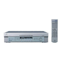
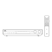
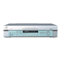
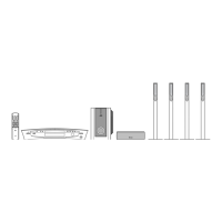
RX-E100RSL/RX-E100RSB
1-11
1~8
9
10
11
12
13
14
15
16
17
18
19
20
21
22
23
24
25~32
33
34,35
36
37,38
39
40
41
42
43
44
45,46
47
48
49
50
51,52
53
54~63
64,65
66
67
68
69,70
71
72
73~80
81
82
83
84
85
86
87
88
89
90~93
94
95~100
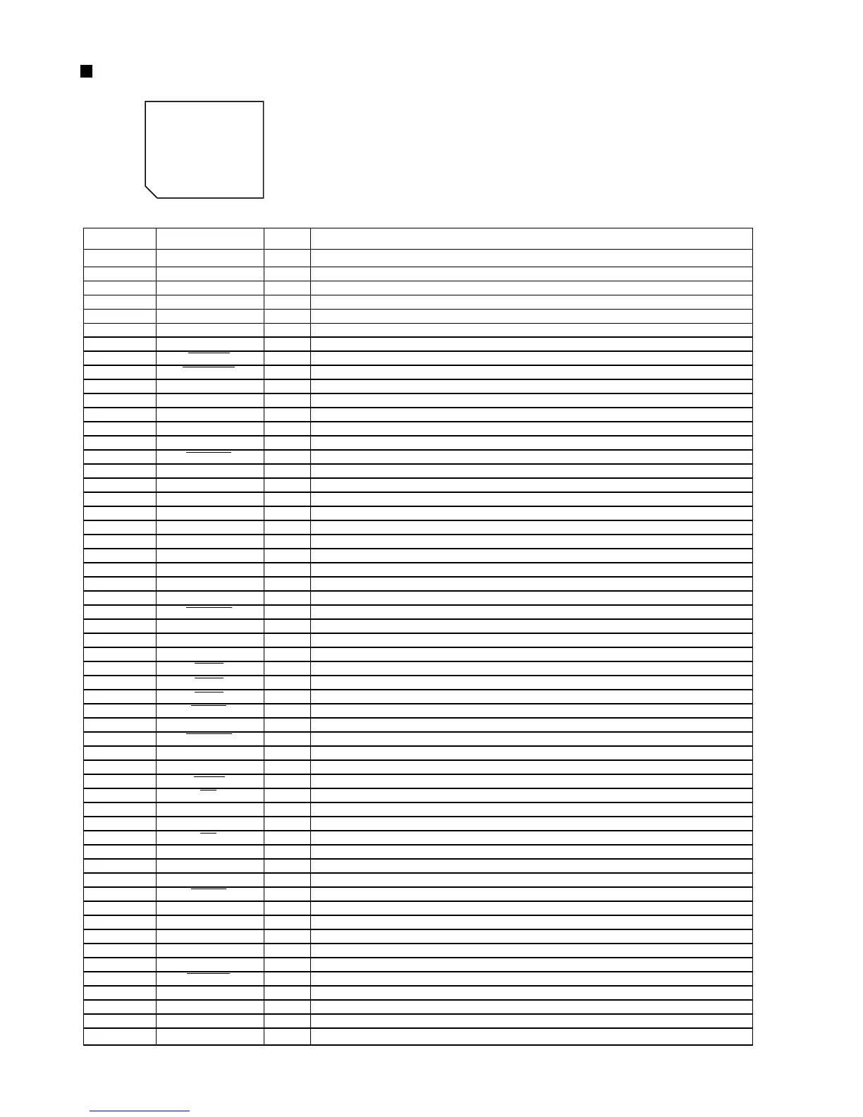
VDD
X2
X1
VSS
XT2
XT1
RESET
AUTODATA
LOCK
DIGITAL0
FORMAT
CHANNEL
ERR
RSTDET
AVDD
AVREF0
AVSS
AV REF1
RX,TX
DSPCOM
DSPSTS
DSPCLK
DSPRDY
MIDIO_IN/OUT
MICK
MICS
MILP
MIACK
DSPRST
CDTI/CDTO
CCLK
CS
XTS
PD
GND
VDD
3D-ON
3D-ON
ANA/T-TONE
REF-MIX
D.MUTE
S.MUTE
ASW1~4
TEST
Non connect
Power supply terminal
Connecting the crystal oscillator for system main clock
Connecting the crystal oscillator for system main clock
Connect to GND
Connecting the crystal oscillator for system sub clock
Connecting the crystal oscillator for system sub clock
System reset signal input
Output of DSP to general-purpose port
Output of DSP to general-purpose port
Output of DSP to general-purpose port
Output of DSP to general-purpose port
Output of DSP to general-purpose port
Output of DSP to general-purpose port
Reset signal input
Power supply terminal
Connect to GND
Connect to GND
Connect to GND
Non connect
Power supply terminal
Not use
Non connect
Communication port from IC701
Status communication port to IC701
Clock input from IC701
Ready signal input from IC701
Non connect
Interface I/O terminal with microcomputer
Interface I/O terminal with microcomputer of clock signal
Interface I/O terminal with microcomputer of chip select
Interface I/O termonal with microcomputer
Interface I/O termonal with microcomputer
Non connect
Reset signal output of DSP
Non connect
Interface I/O terminal with microcomputer
Interface I/O terminal with microcomputer of clock signal
Interface I/O terminal with microcomputer of chip select
OSC Select
Non connect
Reset signal output
Connect to GND
Non connect
Power supply
Non connect
Switch at output destination of surround channel
Test tone control
Control at output destination of LFE channel
Non connect
Mute of the digital out terminal is controlled
Mute of the audio signal is controlled
Non connect
Selection of digital input selector
Test terminal
Non connect
-
-
O
I
-
O
I
I
I
I
I
I
I
I
I
-
-
-
-
-
-
-
-
I
O
I
I
-
I/O
O
O
O
O
-
O
-
I/O
O
O
O
-
O
-
-
-
-
O
O
O
-
O
O
-
O
-
-
Pin No. Symbol I/O Function
75 ~ 51
1 ~ 25
76
100
~
50
26
~
1.Pin layout
2.Pin function
UPD784215AGC103 (IC671) : UNIT CPU
 Loading...