EasyManua.ls Logo

JVC RX-ES1SL Service Manual

JVC RX-ES1SL
51 pages
To Next Page IconTo Next Page
Page #1 background imageLoading...
Page #1 background image
SERVICE MANUAL
COPYRIGHT © 2003 VICTOR COMPANY OF JAPAN, LIMITED
No.MB105
2003/11
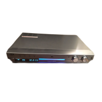
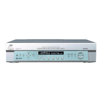
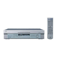
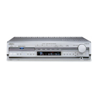
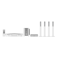
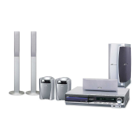
HOME CINEMA CONTROL CENTER
MB105200311
RX-ES1SL
TABLE OF CONTENTS
1 PRECAUTION. . . . . . . . . . . . . . . . . . . . . . . . . . . . . . . . . . . . . . . . . . . . . . . . . . . . . . . . . . . . . . . . . . . . . . . . . 1-3
2 SPECIFICSERVICE INSTRUCTIONS . . . . . . . . . . . . . . . . . . . . . . . . . . . . . . . . . . . . . . . . . . . . . . . . . . . . . . 1-4
3 DISASSEMBLY . . . . . . . . . . . . . . . . . . . . . . . . . . . . . . . . . . . . . . . . . . . . . . . . . . . . . . . . . . . . . . . . . . . . . . . 1-5
4 ADJEUTMENT . . . . . . . . . . . . . . . . . . . . . . . . . . . . . . . . . . . . . . . . . . . . . . . . . . . . . . . . . . . . . . . . . . . . . . . 1-11
5 TROUBLESHOOTING . . . . . . . . . . . . . . . . . . . . . . . . . . . . . . . . . . . . . . . . . . . . . . . . . . . . . . . . . . . . . . . . . 1-12
Area suffix
A ------------------------- Australia

Other manuals for JVC RX-ES1SL

Questions and Answers:

JVC RX-ES1SL Specifications

General IconGeneral
Channels5.1
Audio Formats SupportedDolby Digital, DTS
TunerAM/FM
Frequency Response20 Hz - 20 kHz
Signal-to-Noise Ratio100 dB
Speaker Impedance6-16 ohms
TypeReceiver
Inputs1 x Optical, 1 x Coaxial
Outputs1 x Subwoofer
Input Sensitivity/Impedance200 mV/47 kΩ

Summary

Safety and Precautions

Safety Precautions and Warnings

General safety guidelines, warnings, cautions, and critical component identification for safe operation and repair.

Specific Service Instructions

Disassembly Procedures

Main Body Section Disassembly

Procedures for removing the top cover, front panel, and rear panel from the main body.

Component Removal Procedures

Steps for removing the tuner, digital input board, and digital output board.

Board and Power Supply Removal

Procedures for removing the AC power supply, DC power board, main board, and amp board.

Ancillary Component Removal

Steps for removing the power transformer, fan motor, rectifier board, and headphone jack board.

Front Panel Component Removal

Procedures for removing the FL board, volume board, and SW board from the front panel assembly.

Adjustment Procedures

Troubleshooting Guide

Schematic Diagrams

Block Diagram

Overall system block diagram illustrating component interconnections and signal flow.

Standard Schematic Diagrams

Detailed schematic diagrams for various sections like primary, regulator, speaker terminal, and PWM modulator.

Printed Circuit Board Layouts

Layouts and component placement for front, volume, DC power, SW, FL, and AC power supply boards.

Parts List

Exploded View and General Parts List

Visual exploded view of the unit with numbered parts and their corresponding list.

Electrical Parts List

Detailed list of electrical components (ICs, transistors, resistors, capacitors) with part numbers and descriptions.

Packing Materials and Accessories

List and diagrams of packing materials and included accessories like remote control, batteries, and manuals.