(No.MB105)1-7
3.1.7 Removing the AC power supply board
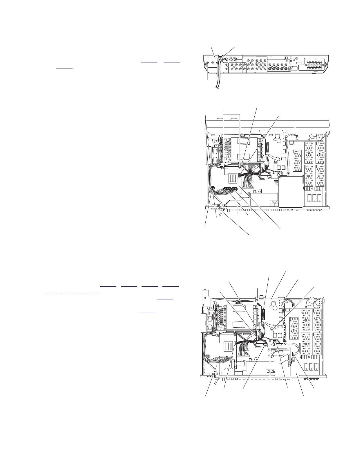
(See Figs.8 and 9)
• Prior to perform the following procedures, remove the top
cover and tuner.
(1) From the top side of the main body, cut the tie band and
disconnect the wires from the connectors CN203
to CN205
and CN218 on the AC power supply board.
(2) From the back side of the main body, remove the two
screws J attaching the AC power supply board. (See Fig.8)
(3) Remove the three screws K attaching the AC power supply
board.
(4) Remove the fasteners from the reverse side of the AC
power supply board.
Reference:
• After attaching the AC power supply board, bundling the
wires using the new tie band.
Fig.8
Fig.9
3.1.8 Removing the DC power board
(See Fig.10)
• Prior to perform the following procedures, remove the top
cover, front panel assembly and digital input board.
(1) From the top side of the main body, disconnect the wires
from the connectors (CN201
, CN206, CN207, CN211,
CN510
, CN520, CN711) on the DC power board.
(2) Disconnect the parallel wire from the connector CN712
on
the amp. board.
(3) Disconnect the wire from the connector CN218
on the AC
power supply board.
(4) Remove the two screws L attaching the DC power board.
Fig.10
Strain relief
J
Rear panel
CN204
CN203
Power cord
CN218
AC power supply board
Wire clamp
K
K
Tie band
Fastener
CN205
CN520
CN510
CN201
CN711
CN712
CN211CN207
CN206
Amp. board
CN218
L
L
DC power board
AC power supply board
 Loading...