Do you have a question about the JVC SP-DXU10C and is the answer not in the manual?
Essential safety measures to prevent hazards during servicing.
Critical warnings regarding safety standards and component replacement.
Identification of safety-critical components for replacement.
Measures to prevent electrostatic discharge damage to sensitive components.
Crucial information and warnings related to laser product safety.
Instructions for disassembling the main body of the unit.
Detailed procedure for removing the DVD changer mechanism.
Detailed steps for removing the main circuit board.
Procedures for disassembling the DVD changer mechanism.
Detailed instructions for removing the DVD servo board.
Procedure for removing the DVD traverse mechanism assembly.
Detailed instructions for removing the DVD pickup unit.
Steps for reattaching the DVD pickup unit.
Detailed steps for removing the lifter assembly.
Key considerations before servicing the DVD section.
Steps for initializing the DVD module EEPROM.
Various diagnostic modes for checking DVD functions.
Part 1 of the DVD section schematic for DX-U10 and DX-U8.
Part 2 of the DVD section schematic for DX-U10 and DX-U8.
Part 3 of the DVD section schematic for DX-U10 and DX-U8.
Part 1 of the DVD section schematic for DX-U6.
Part 2 of the DVD section schematic for DX-U6.
| Impedance | 4 Ohms |
|---|---|
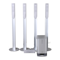
| Subwoofer | Yes |
| Satellite Speakers | 2 |
| Power Supply | AC 220-240V, 50/60Hz |
| Input | 3.5mm Stereo Jack |