(No.MB108)1-13
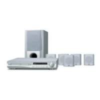
3.3.4 Removing the clamper base
(See Fig.4)
(1) From the top side of the DVD mechanism assembly, re-
move the four screws A attaching the clamper base.
(2) Remove the clamper base from the bosses d of the loading
base in an upward direction, remove the clamper base
from the sections e while sliding it in the direction of the ar-
row.
Fig.4
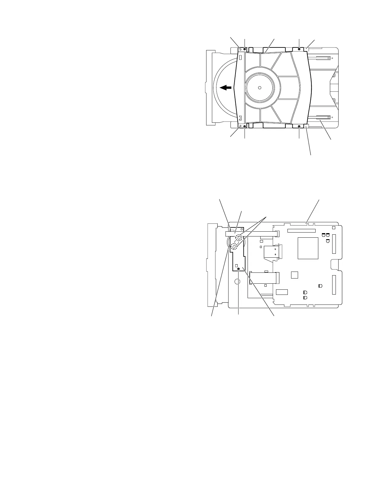
3.3.5 Removing the tray drive board
(See Fig.5)
• Prior to performing the following procedures, remove the
clamper base.
(1) From the bottom side of the DVD mechanism assembly, re-
move the solders from the soldered sections f on the tray
drive board.
(2) Remove the screw B attaching the tray drive board to the
DVD mechanism assembly.
Fig.5
Clamper base
AA
Boss d
Boss d
A A
Section e
Section e
Loading base
Motor
Tray drive board
DVD mechanism assembly
B
Soldered
sections f
Connector
Card wire

 Loading...