(No.MB108)1-19
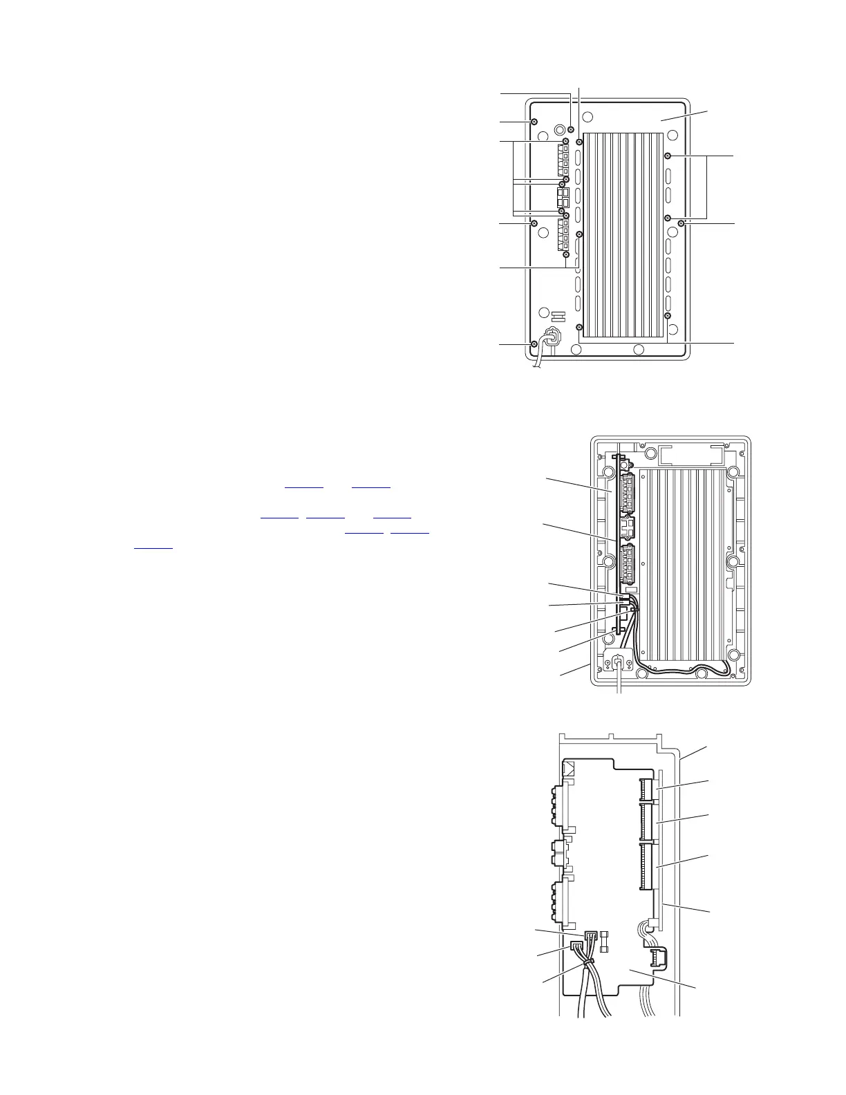
3.4.2 Removing the rear panel
(See Fig.3)
• Prior to performing the following procedures, remove the am-
plifier assembly.
(1) Remove the four screws C, twelve screws D and screw E
attaching the rear panel.
(2) Take out the rear panel from the amplifier assembly.
Fig.3
3.4.3 Removing the SP terminal board
(See Figs.4 and 5)
• Prior to performing the following procedures, remove the am-
plifier assembly and rear panel.
(1) From the top side of the amplifier assembly, disconnect the
card wires from the connectors CN101
and CN102 on the
mother board. (See Figs.4 and 5)
(2) Disconnect the connectors CN401
, CN403 and CN404 on
the SP terminal board from the connectors CN501, CN503
and CN504 on the mother board while lifting the SP termi-
nal board upward. (See Fig.5)
(3) Take out the SP terminal board from the amplifier assem-
bly.
Reference:
When attaching the SP terminal board, insert the SP terminal
board in the section a of the barrier.
Fig.4
Fig.5
C
D
D
D
C
C
E
D
Rear panel
C
D
Section a
Amplifier
assembly
Tie band
SP terminal
board
Mother
board
CN102
CN101
Amplifier
assembly
Tie band
SP terminal
board
Mother
board
CN501
CN401
CN403
CN404
CN503
CN504
CN101
CN102

 Loading...