TH-A5R
1-21
3. Pin function
Symbol
VD1,VD2,VD3
DGND1,DGND2,DGND3
AUDATA3,XMT958
WR,DS,EMWR,GPIO10
RD,R/W,EMOE,GPIO11
A1,SCDIN
A0,SCCLK
DATA7,EMAD7,GPIO7
DATA6,ENAD6,GPIO6
DATA5,EMAD5,GPIO5
DATA4,EMAD4,GPIO4
DATA3,EMAD3,GPIO3
DATA2,EMAD2,GPIO2
DATA1,EMAD1,GPIO1
DATA0,EMAD0,GPIO0
CS
SCDIO,SCDOUT,PSEL,GPIO9
ABOOT,INTERQ
EXTMEM,GPIO8
SDATAN1
SCLKN1,STCCLK2
LRCLKN1
CMPDAT,SDATAN2
CMPCLK,SCLKN2
CMPREQ,LRCLKM2
CLKIN
CLKSEL
FILT1
TILT2
VA
AGND
RESET
DC
DD
AUDATA2
AUDATA1
AUDATA0
LRCLK
SCLK
MCLK
Pin No.
1,12,23
2,13,24
3
4
5
6
7
8
9
10
11
14
15
16
17
18
19
20
21
22
25
26
27
28
29
30
31
32
33
34
35
36
37
38
39
40
41
42
43
44
Function
Digital Positive Supply
Digital Supply Ground
SPDIF Transmitter Output, Digital Audio Output 3
Host write strobe or Host data strobe or External Memory write enable or
General purpose input& output Number 10
Host Parallel Output Enable or Host Parallel R/W or External Memory Output
Enable or General Purpose Input & Output Number11
Host Address Bit One or SPI Serial Control Data Input
Host Parallel Address Bit Zero or Serial Control Port Clock
Data Bus
Data Bus
Data Bus
Data Bus
Data Bus
Data Bus
Data Bus
Data Bus
Host Parallel Chip Select, Host Serial SPI Chip Select
Serial Control Port Data Input and Output, Parallel Port Type Select
Control Port Interrupt Request, Automatic Boot Enable
External Memory Chip Select or General Purpose Input & Output Number 8
PCM Audio Data Input Number One
PCM Audio Input Bit Clock
PCM Audio Input Sample Rata Clock
PCM Audio Data Input Number Tow
PCM Audio Input bit Clock
PCM Audio Input Sample Rate Clock
Master Clock Input
DSP Clock Select
Phase Locked Loop Filter
Phase-Locked Loop Filter
Analog Positive Supply
Analog Supply Ground
Master Reset Input
Reserved
Reserved
Digital Audio Output 2
Digital Audio Output 1
Digital Audio Output 0
Audio Output Sample Rate Clock
Audio Output Bit Clock
Audio Master Clock
–
+
+
–
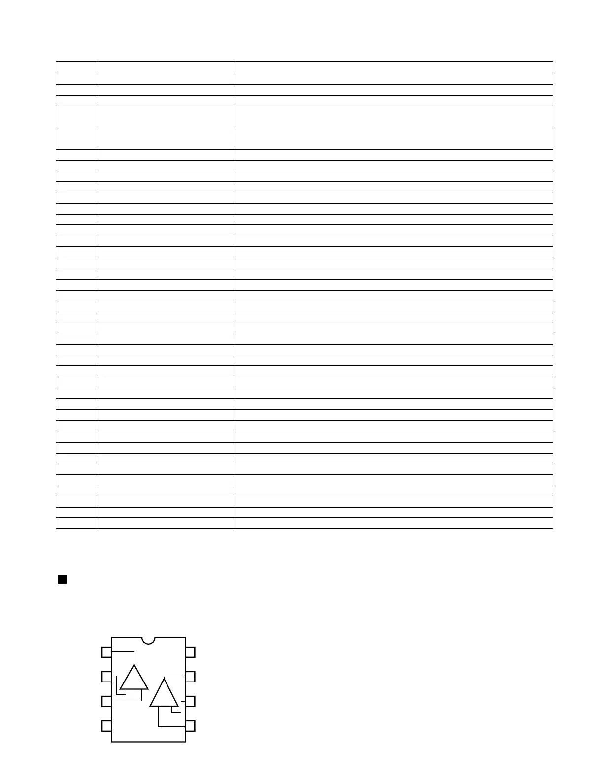
1
2
3
4
8
7
6
5
OUT1
– IN1
+ IN1
V
EE
V
CC
OUT2
– IN2
+ IN2
1ch
2ch
BA4560 (IC2, IC5, IC6, IC7, CIC11, CIC13, FIC2, FIC4, FIC5, FIC6, FIC11, RIC11, RIC13)
: Dual op amp.
1.Pin layout
 Loading...