1-7
UX-A52R
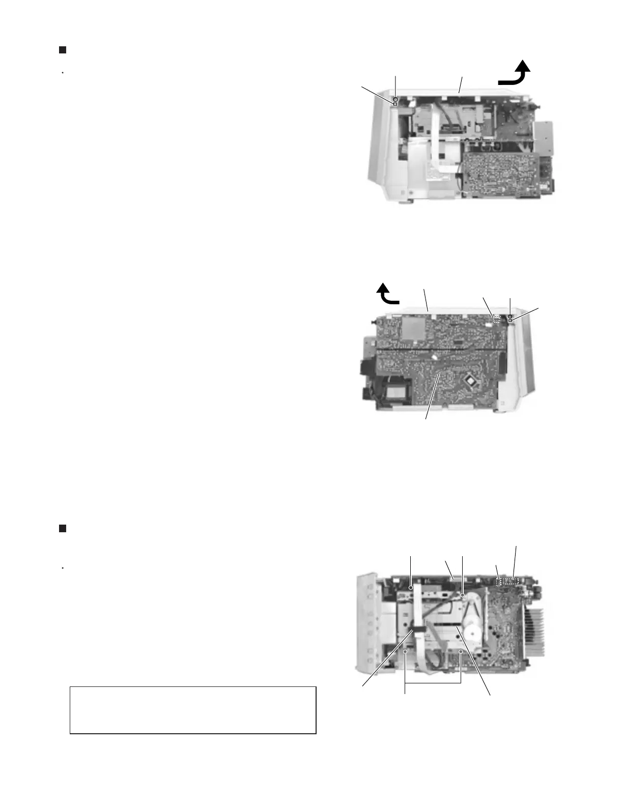
Prior to performing the following procedure, remove
the rear cover and the side panels.
Remove the two screws D on each side of the body.
Release the two joints b on each side of the body
and remove the top panel in the direction of the
arrow.
Disconnect the card wires from connector CN705 on
the system control board on the left side of the body.
1.
2.
3.
Removing the top panel (See Fig.6 and 7)
Prior to performing the following procedure, remove
the rear cover, the side panels and the top panel.
Disconnect each wire from connector CN706, CN715
and CN716 on the system control board on top of the
body.
Remove the four screws E retaining the cassette
mechanism assembly section on top of the body.
1.
2.
Removing the cassette mechanism
assembly section (See Fig.8)
Reference: If necessary, remove the
spacer marked h and the wire from the
Cassette mechanism assembly section.
REFERENCE:
Fig.7
Fig.8
Fig.6
Top panel
Top panel
D
CN705
D
System control board
CN715
System control board
CN706
E E
Joint b
Joint b
CN716
E
h (spacer)
Cassette mechanism section
 Loading...


