1-8
UX-A52R
Prior to performing the following procedure, remove
the rear cover and the right side panel.
Disconnect the card wire from connector CN1 on the
tuner board on the right side of the body.
Remove the screw G and remove the tuner board
upward while disengaging the three joints c.
1.
2.
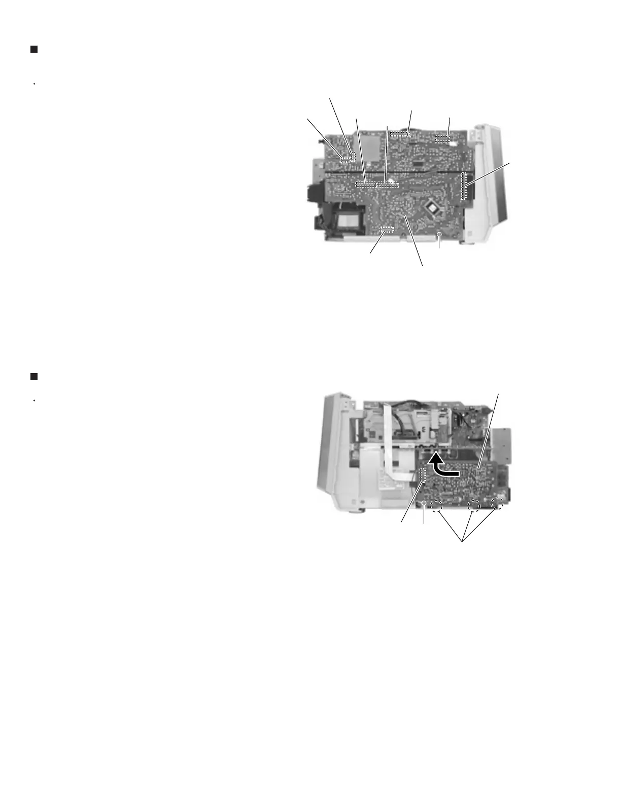
Removing the tuner board (See Fig.10)
Prior to performing the following procedure, remove
the rear cover, the side panels and the top panel.
Disconnect the card wire from connector CN701 and
the wire from connector CN706, CN715, CN716 on
the system control board.
Remove the screw F on the left side of the body.
Disconnect connector CN709, CN711 and CN712 on
the system control board from the body outward.
Disconnect the card wire from connector CN704 on
the underside of the system control board.
1.
2.
3.
4.
Removing the system control board
(See Fig.9)
Fig.9
Fig.10
System control board
F
CN712
CN711
CN701
CN709
CN704
CN1
G
Joints c
Tuner board
CN715
CN716
CN706
 Loading...


