1-31
UX-A70MD
Key to press Mode
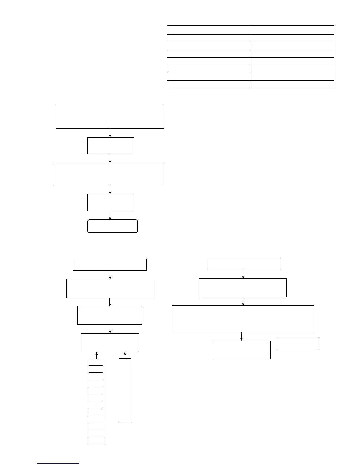
(6) Setup of the TEST MODE 2
(7) Indication of variation in the pickup adjustment value
ASG
TRG
TRB
FOB
FGR
FEXP
FGC
FG
TGR
TEXP
TGC
TG
-1
-2
:
-128
127
126
:
1
0
(8) Indication of the C1 error
FL indication*
X X Y Y Z Z
For investigating the mode in which an error
occurred during the disk adjustment, freeze the
set in the mode by pressing the proper key
(refer to the table on the right) on the remote
controller before cancelling the TEST MODE 1.
SLEEP key (Remote controller)
"6" key (Remote controller)
"7" key (Remote controller)
"8" key (Remote controller)
"9" key (Remote controller)
STOP key (Remote controller)
EJECT key (Main unit)
FOCUS SEARCH
PIT ROUGH SERVO
GROOVE ROUGH SERVO
TRACKING ON
TRACKING OFF
STOP
EJECT
While pressing both the POWER key and
FORWARD STOP key on the main unit,
turn on the primary power supply.
FL indication MD
TEST MODE 1
While pressing the STOP key on the main
unit, press the FM/AM key on the main
unit double. The TEST MODE 2 is set up.
FL indication MD
TEST MODE 2
Setup is complete.
Set up the TEST MODE 2.
Press the MD OPEN/CLOSE key
and insert the MD test disk.
Press the "6" key on the
remote controller.
FL indication*
XXXXX - XXXX
* Each time the
"6" key on the
remote
controller is
pressed, the
indication
changes from
ASG to TRG,
from TRG to
TRB, and so
on as shown
in the figure.
Set up the TEST MODE 2.
Press the MD OPEN/CLOSE key
and insert the MD test disk.
Press the "8" key on the remote controller. Counting of
number of C1 errors starts and it continues until it
counts up the maximum number of C1 errors with
indication (maximum number of error indication is 432).
200 Hz or less
(9) Cancel of the TEST MODE
(The cancel operation is common to the TEST
MODE 1 and 2.)
Cut off the primary power supply to cancel the
TEST MODE.
 Loading...