1-41
UX-A70MD
1
2
3
4
5
6
7
8
9
10
Vreg IN
Reg GN
NC
VG
SVCC
PDGND
EFM
MUTE
NC
NC
Regulator input and regulator
power supply
Regulator GND
Non connect
Voltage input for power MOS drive
EFM high level output voltage
Pre-driver GND
EFM signal input
Mute control (Low active)
Non conncet
Non connect
11
12
13
14
15
16
17
18
19
20
NC
VOD2
VSS
VOD1
VOS1
VDD
VOS2
Reg DRV
Reg OUT
Reg NF
Non connect
Sync.output (Lower power MOS,drain)
"H"bridge GND (Lower power MOS,source)
Sync.output (Lower power MOS,drain)
Source output (Upper power MOS,source)
"H" bridge power supply terminal
(Upper power MOS,source)
Source output (Upper power MOS,source)
External PNP drive output for regulator
Reglator output (Emitter follower output)
Regulator feedbaack terminal
I
-
-
I
O
-
I
I
O
O
-
O
-
O
O
-
O
O
O
-
Pin
No.
Pin
No.
Symbol Symbol
I/O I/O
Function Function
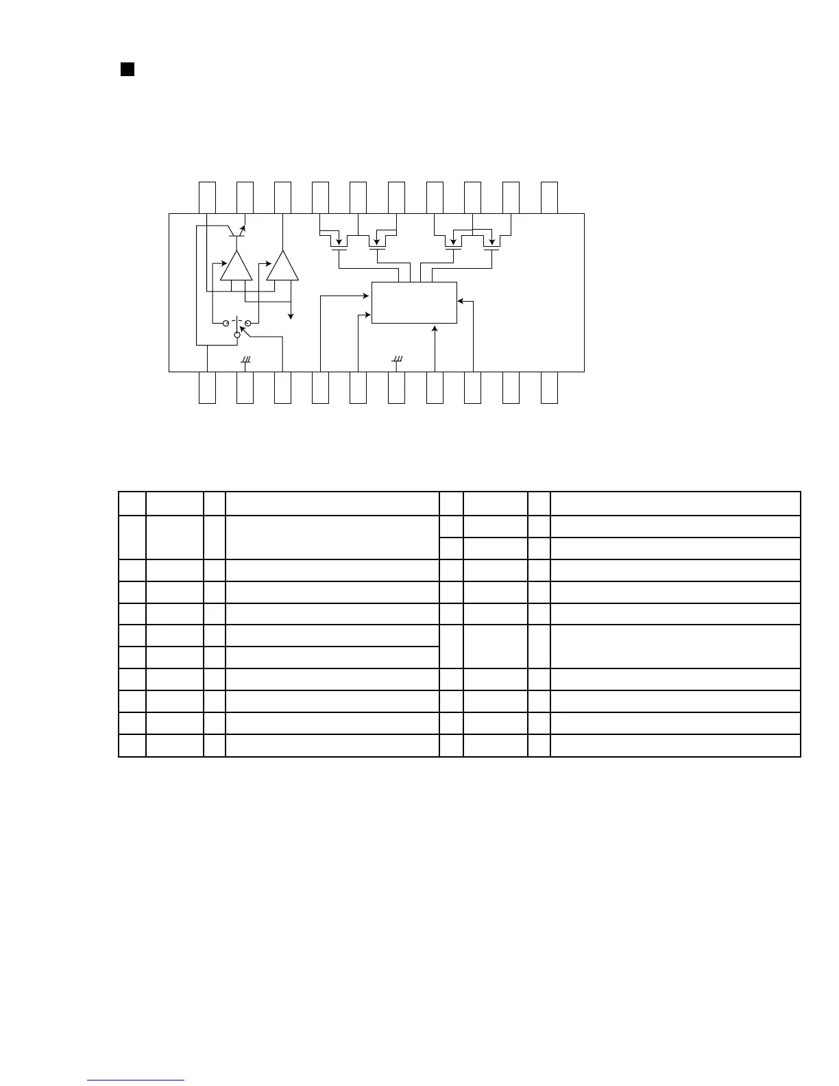
2.Pin function
BD7910FV-X (IC450) : Pre driver
1.Block diagram
20 19 18 17 16 15 14 13 12 11
1 2 3 4 5 6 7 8 9 10
Vregin
VG
SVcc
Pre driver
EFM
Mute
- +
- +
 Loading...