7
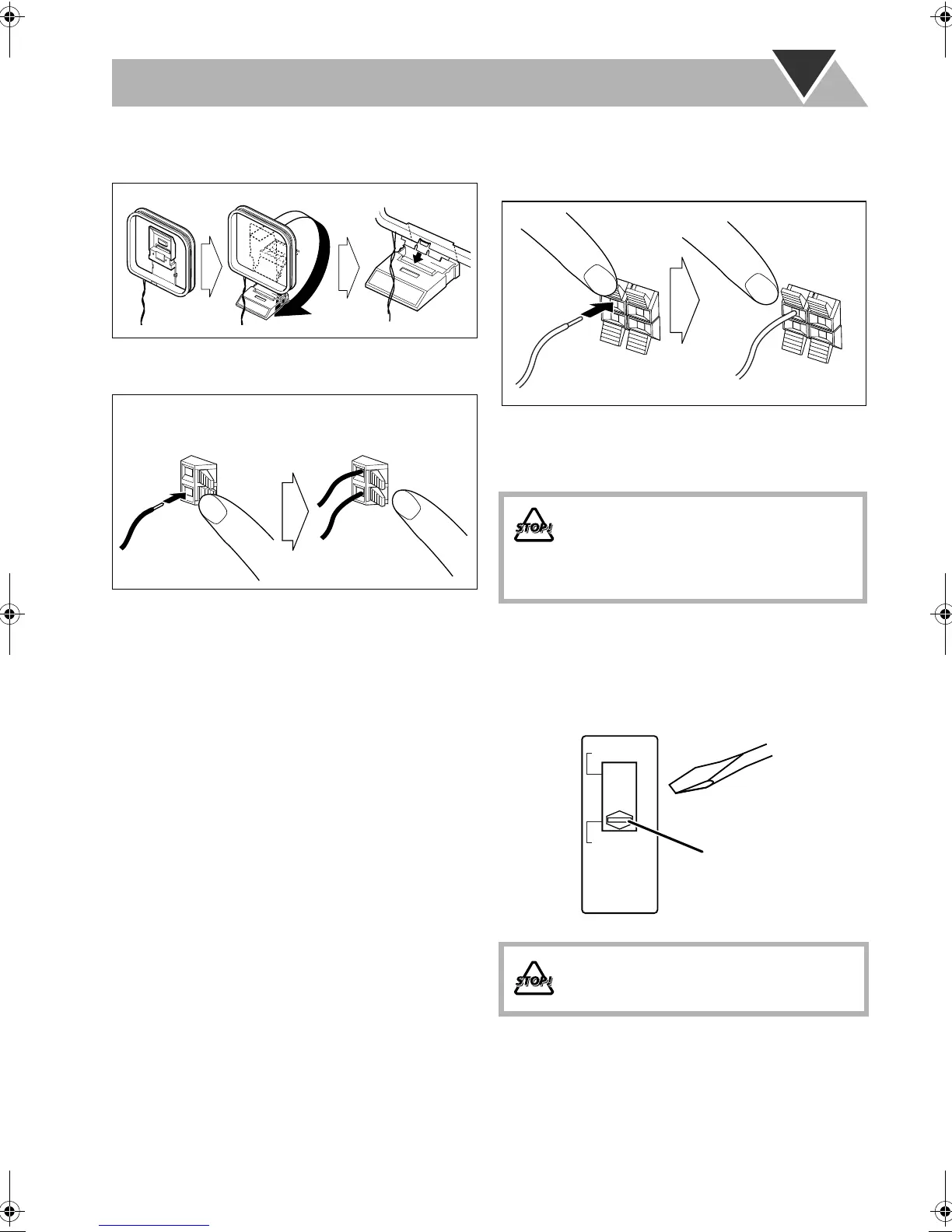
To assemble and connect the AM loop antenna
To assemble the AM loop antenna
To connect the AM loop antenna
Make sure to connect the wire correctly.
• If the AM loop antenna wire or speaker cords are covered
with vinyl, remove the vinyl to expose the tip of the
antenna by twisting the vinyl.
• Make sure the antenna conductors do not touch any other
terminals, connecting cords and power cord. Also, keep the
antennas away from metallic parts of the System,
connecting cords, and the AC power cord. This could cause
poor reception.
To connect the speaker cords
Make sure the both speakers are connected correctly and
firmly.
When connecting the speaker cords, match the polarity of
the speaker terminals: The cord with black stripe to (–), the
cord without stripe to (+).
Adjusting the voltage selector
Use a screwdriver to slide the voltage selector so that the
voltage marker is pointing at the same voltage as where you
are plugging in the unit. (See also the back cover page.)
1 Hold
2 Insert
3 Release
• DO NOT connect more than one speaker to
each terminal.
• DO NOT allow the conductor of the speaker
cords to be in touch with the metallic parts of
the System.
DO NOT plug in before setting the voltage
selector on the rear of the unit and all
connection procedures are complete.
1 Hold
2 Insert
3 Release
220V-240V
AC VOLTAGE
SELECTOR
110V-127V
Voltage marker
UX-G50[UJ].BOOK Page 7 Monday, June 5, 2006 5:59 PM
 Loading...