2-9
UX-G6/FS-G6
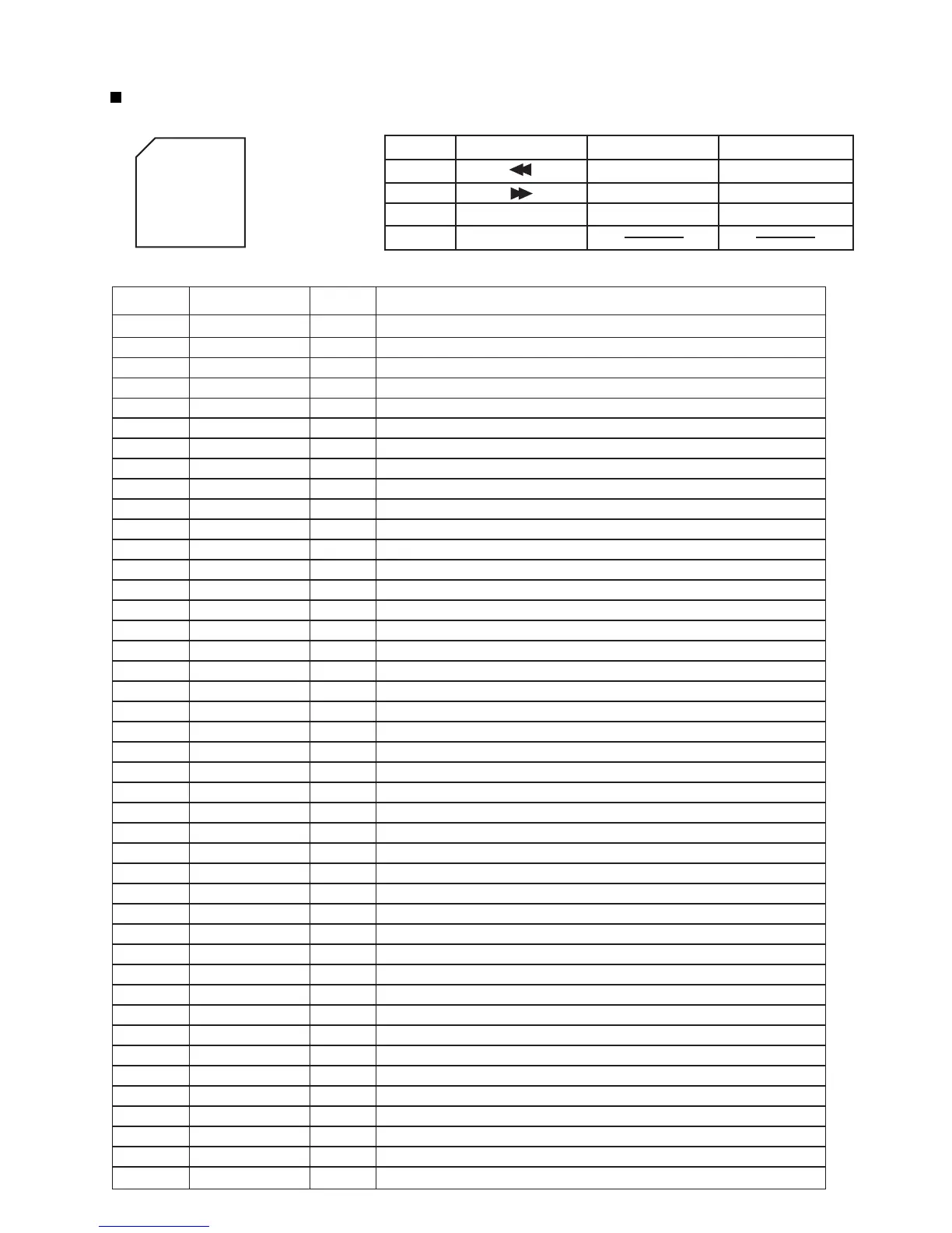
UPD780023 (IC701) : System control
1,2
3,4
5
6
7
8
9
10
11
12
13
14
15
16
17
18
19
20
21
22
23
24
25
26
27
28~32
33
34
35
36
37
38
39
40,41
42
43~46
47~49
50~59
60
61
62
63
64
JOG1A,B
JOG2A,B
CLOSE
OPEN
CLOSESW
OPENSW
VSS0
VDD0
FLOFF
FLBK
FLLAT
FLSOUT
FLSLK
COMMAND
STATUS
CLK
READY
P.ON
SMUTE
VDD1
AVSS
PRT
DLOCK
PANELKEY
AVREF
AVDD
RESET
XT2
XT1
VPP
X2,X1
VSS1
KEYI1~4
KEYO0~3
POWERLED
STBYLED
LEDDIM
JOG1BLU
JOG2BLU
Rotary encoder input from JOG1(JS701)
Rotary encoder input from JOG2(JS702)
Front panel close control signal output to IC901
Front panel open control signal output to IC901
Front panel close switch detection terminal from SW912
Front panel open switch detection terminal from SW911
Connect to GND
Power supply
Non connect
FL OFF output (At Eco mode)
FL driver I/F (valiable by dimmer)
FL driver I/F (latch)
Non connect
FL driver I/F
FL driver I/F
System micom I/F to XT-UXG6
Status signal output (System micom I/F to XT-UXG6)
Clock signal input (System micom I/F to XT-UXG6)
Ready input (System micom I/F to XT-UXG6)
Power ON control output H:Power ON
System mute
Power supply
Connect to GND
Speaker protector
Panel lock : 95h~00h(200ms)
Connect to GND
Key input (S7001~S7004)
Power supply +5V (Standard AD)
Power supply +5V (Connect to Vdd)
Reset input
Non connect
Connect to GND
Connect to GND
Oscllation terminal (8MHz)
Connect to GND
Key matrix input terminal
Key matrix output terminal
Connect to GND
Power ON LED control terminal H:Lighting
Power OFF LED control terminal H:Lighting
LED dimmer control L:It is dark.
LED control for JOG1(JS701) Lighting when power ON, Blinking when operating
LED control for JOG2(JS702) Lighting when power ON, Blinking when operating
I
I
O
O
I
I
-
-
-
O
O
O
-
O
O
I
O
I
I
O
O
-
-
I
I
-
I
-
-
I
-
-
-
I/O
-
I
O
-
O
O
O
O
O
Pin No. Symbol I/O Function
KEYI1
KEYI2
KEYI3
KEYI4
KEYO1
PLAYMODE
RECMODE
KEYO2
CLOCK/TIMER
SET
CANCEL
KEYO3
TITLE/EDIT
DISPLAY/CHARA.
ENTER
2.Key matrix1.Pin layout
3.Pin function
1
16
48
33
64 ~ 49
17 ~ 32
~
~

 Loading...