(No.MB211)1-11
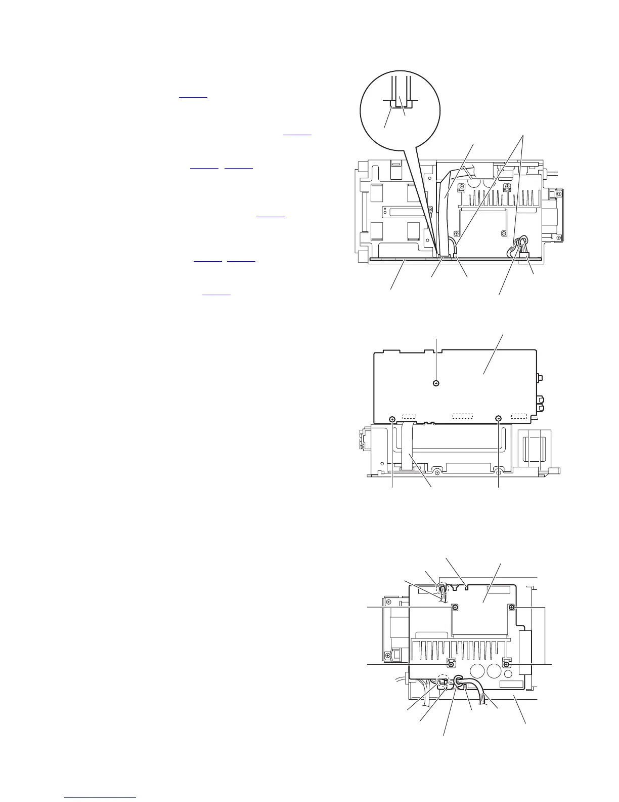
3.1.6 Removing the micon board
(See Figs.9 and 10)
• Remove the metal cover, front panel assembly and rear panel.
(1) From the top side of the main body, disconnect the card
wire from the connector CN766
on the micon board. (See
Fig.9.)
Reference:
When connecting the card wire to the connector CN766
,
fix the card wire with the spacer as before.
(2) From the forward side of the micon board, disconnect the
wire from the connectors (CN750
, CN760) on the micon
board. (See Fig.9.)
Reference:
When reassembling, fix the wire with the wire holder af-
ter connecting the wire to the connector CN760
on the
micon board as before. (See Fig.9.)
(3) From the right side of the main body, remove the three
screws K attaching the micon board. (See Fig.10.)
(4) Disconnect the connectors (CN761
, CN762) on the micon
board toward this side. (See Fig.10.)
(5) From the forward side of the micon board, disconnect the
card wire from the connectors CN765
. (See Fig.10.)
Fig.9
Fig.10
3.1.7 Removing the power amplifier board
(See Fig.11)
• Remove the metal cover, front panel assembly, rear panel,
power supply board and micon board.
(1) From the top side of the main body, remove the wire holder
and tie band fixing the wire 1.
(2) Remove the four screws L attaching the power amplifier
board.
Reference:
• When attaching the power amplifier board, align the sections
f of the main chassis in the slots of the power amplifier
board.
• After attaching the power amplifier board, pass the wire 1
through the section g of the power amplifier board.
• When reassembling, fix the wire 1 with the wire holder and
new tie band as before.
• When reassembling, pass the wire 2 through the section h
of the power amplifier board.
Fig.11
Micon board
Wire holder
CN766
CN760
CN766
Spacer
CN750
Card wire
Wires
K
Micon board
CN765
CN762
CN761
K
K
Card wire
L
Power amplifier board
L
Wire holder
Wire 1
g
h
Wire 2
L
f
f
Main chassis
Tie band
 Loading...