1-28 (No.MB230)
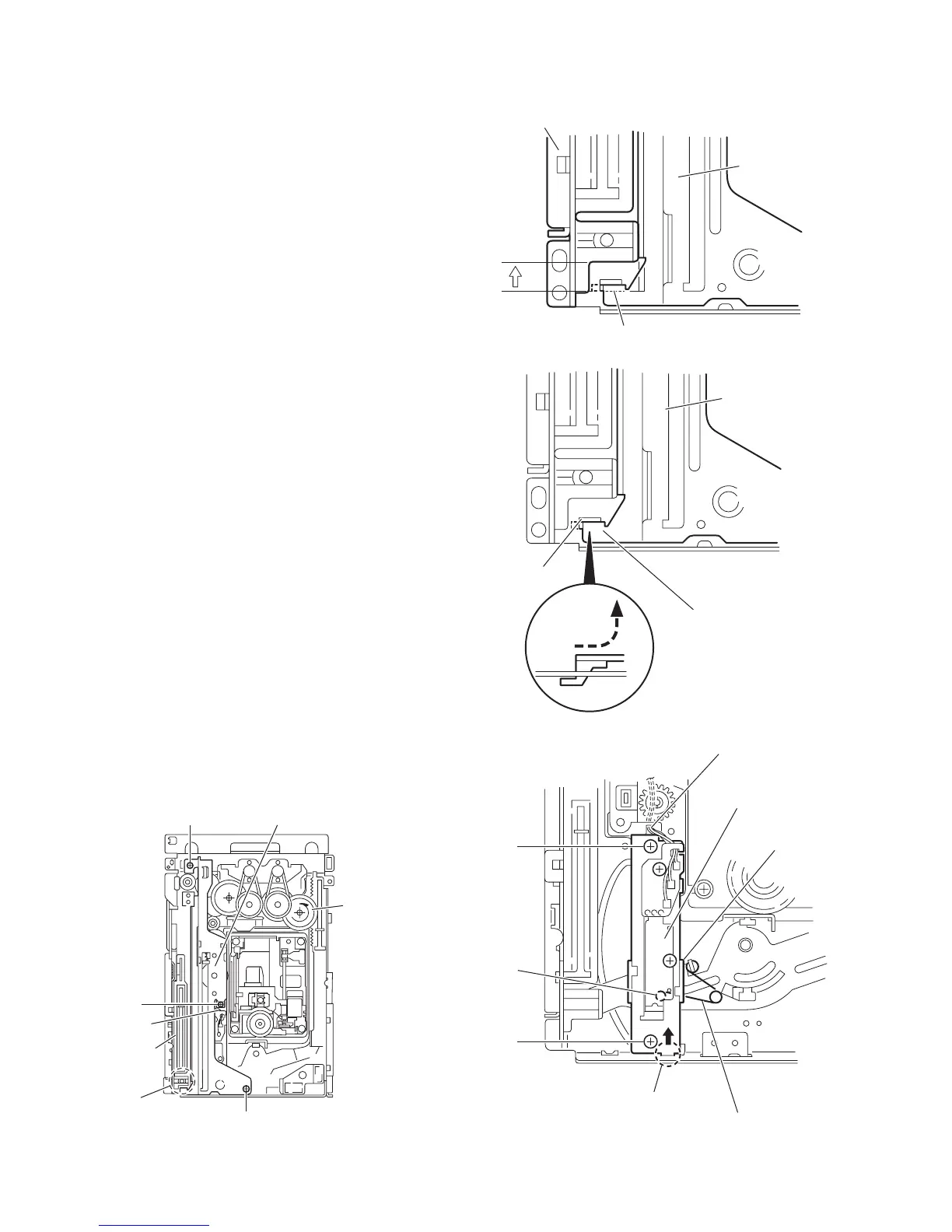
3.2.14 Removing the rack holder and sensor assembly
(See Figs.32 to 38)
• Prior to performing the following procedures, remove the tray
assemblies, side (L), side (R) assembly and lifter assembly.
Reference:
If the slide gear of the DVD changer mechanism assembly
places at joint ad of the rack holder, turn the gear 1 counter-
clockwise to move the slide gear in the direction of the arrow.
Then Remove the rack holder. (See Figs.32 and 33.)
(1) Remove the three screws W attaching the rack holder and
release joint ad from the notch ae. (See Figs.32 and 34.)
Note:
When reattaching the rack holder, do not nip the wires
extending from the sensor assembly. (See Fig.32.)
(2) Remove the two screws X attaching the sensor assembly.
(See Figs.35 and 38.)
(3) Move the sensor assembly in the direction of the arrow to
release from the joint section af. (See Figs.35 and 38.)
(4) Remove the sensor spring attached to the bottom of the
sensor assembly from the boss ag on the slider. (See
Figs.35 and 36.)
(5) Remove the screw Y and Z attaching the sensor board and
SV. resister respectively. (See Fig.37.)
Reference:
Remove the soldered section aj on the sensor board as re-
quired. (See Fig.37.)
Note:
• When reattaching the SV. resister, attach the slider to the
sensor bracket and fit the lever on the bottom of the SV. re-
sister into slot ak of the sensor slider. (See Figs.36 and 37.)
• When reattaching the rack holder, turn the gear 1 clockwise
to move the slide gear and slide lever inside the body in the
direction of the arrow. (See Figs.32 and 38.)
• Let the wire extending from the sensor assembly through
notch ah to the bottom of the DVD changer mechanism as-
sembly. (See Figs.35 and 38.)
• Fit pin am of the slide lever into hole ai of the slider on the
bottom of the sensor assembly while attaching the sensor
spring to the boss ag of the slider. (See Figs.36 and 38.)
• Joint section af of the sensor assembly to the notch an of the
DVD changer mechanism assembly. (See Fig.38.)
Fig.32
Fig.33
Fig.34
Fig.35
ad
W
W
W
Gear 1
Rack holder
Wire
Slide gear
ad
Rack holde
Slide gear
ad
Rack holde
ae
X
X
ah
af
Sensor spring
Sensor assembly
ag
Slider
 Loading...