VS-DT2000
1-11
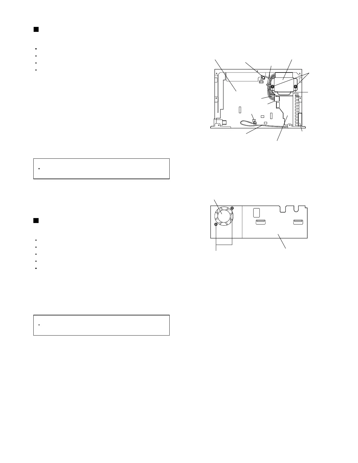
Fig.13
Fig.14
P
R
Fan motor
Bottom chassis
Main board
Treat the wire from the fan motor.
Power amplifier
board
CN191
CN194
CN192
CN181
Fan motor
Washers
Tie band
Wire clamp
Power transformer
Removing the power transformer
(See Fig. 13.)
1.
2.
3.
4.
Disengage the wire clamp and tie band bundling
the wires of the power transformer.
Disconnect the wire from connector CN192 on the
power amplifier board.
Disconnect the wires from connectors CN191 and
CN194 on the main board.
Remove the two screws R and two washers
attaching the power transformer.
Removing the fan motor
(See Figs. 13 and 14.)
1.
2.
Disconnect the wire from connector CN181 on the
main board.
From the right side of the main body, remove the
two screws P attaching the fan motor.
Remove the top lens.
Remove the bottom panel.
Remove the top panel.
Remove the CD mechanism assembly.
[Reference]
After connecting the wires, bundling them
using a wire clamp and tie band.
Remove the top lens.
Remove the bottom panel.
Remove the top panel.
Remove the CD mechanism assembly.
Remove the front panel assembly.
[Reference]
After mounting the fan motor, treat the wire
from the fan motor as shown in fig. 13.
 Loading...