9
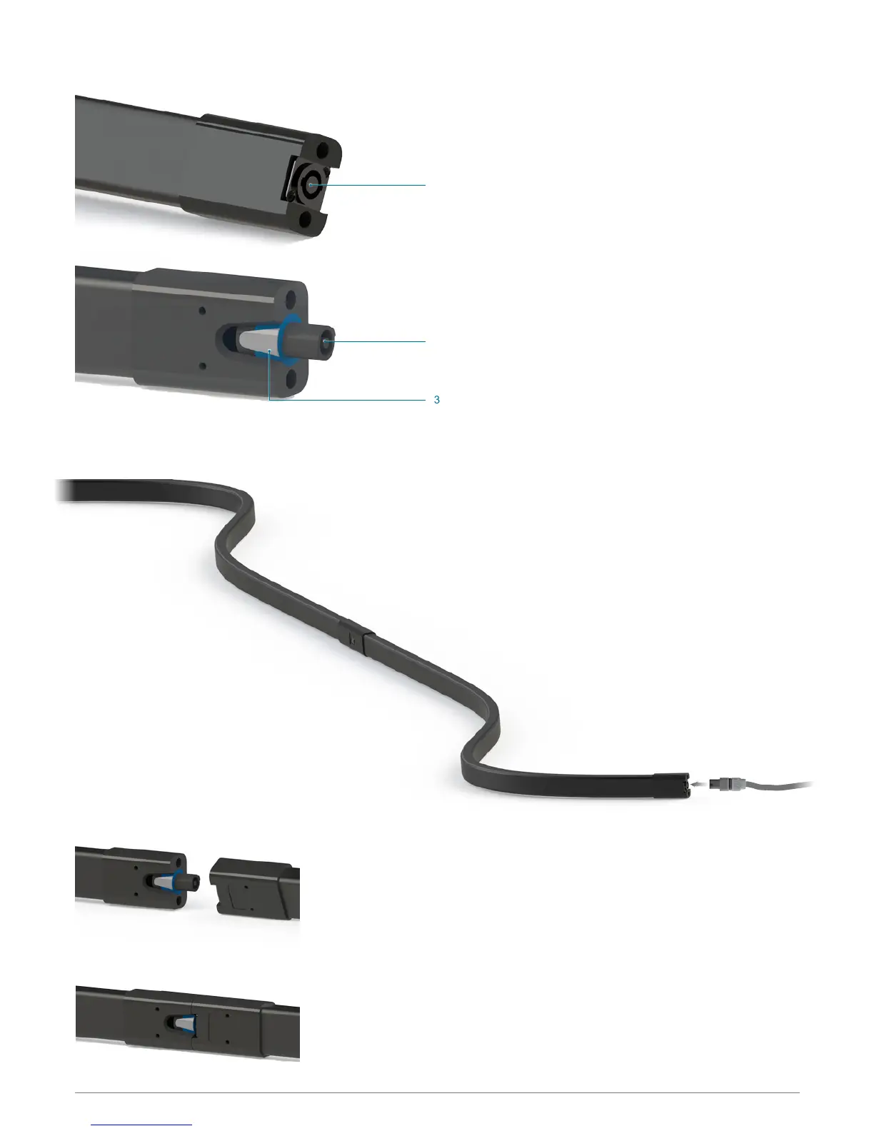
8 CONNECTORS AND SET UP
1
1) Powered signal parallel INPUT. Four-pin female speakon.
2) Powered signal parallel INPUT. For-pin female speakon.
3) Connector secure lock. Pull it back and turn the connector
to unplug it.
img. 1
2
3
Audio power signal on pins 1+/1- of the NL4 connectors is
fed into the speaker, while the signal on pins 2+/2- passes
through from one socket to the other. Thus, the signal can
pass through multiple KAN200 modules without additional
external cabling. Signal on pins 2+/2- can then be easily fed
into another KAN200, another series of KAN200 modules or a
different speaker with the insertion of a K-ANLINK (see p.11).
You can connect a series of up to 16 units (32 m) to a single
channel of a 4Ω amplier.
FEATURES