Device description
18 k4evo707en-2012-07
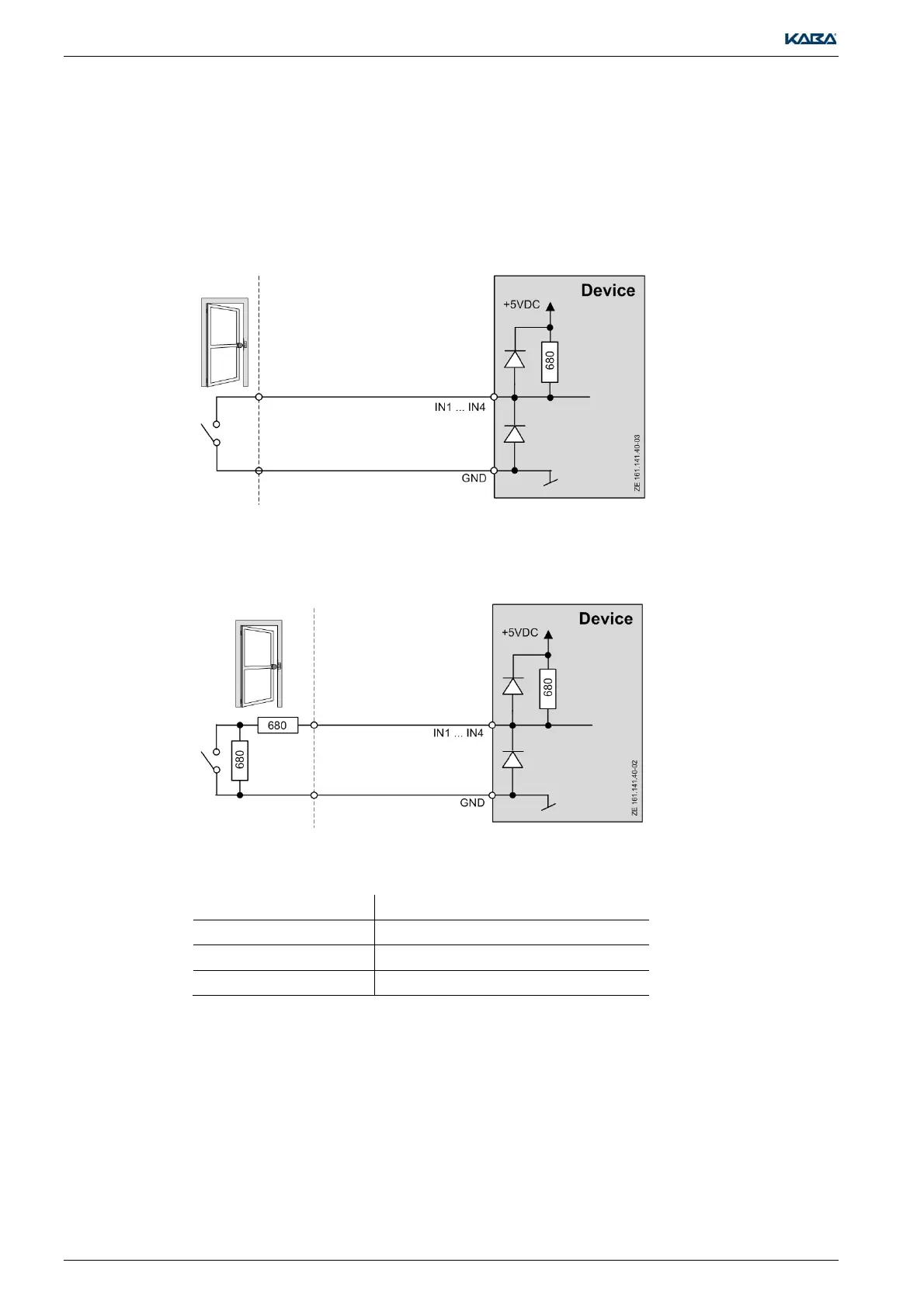
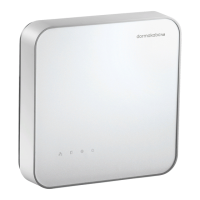
2.5.5 Inputs IN1 and IN2 (5)
The input circuits listed below are valid for IN1 and IN2. They can be connected as inputs with or
without line monitoring. It is possible to define both the line monitoring and the logic for the inputs
on an individual basis in the host system.
DIP switches 3 and 4 are used to define the inputs.
2.5.5.1 Inputs without line monitoring
2.5.5.2 Inputs with line monitoring
For monitoring purposes, the lines must be connected with resistors (R=680Ω, ¼W 2%).
The resistors must be attached directly to the external contact in a tamper-proof way.
2.5.5.3 Connecting the inputs
Terminal numbe
Meaning
6 GND (common ground)
7 Input 1 (REX) Door opener key or door handle contact
8 Input 2 (FC) Frame contact