Do you have a question about the Kaco Powador 10.0 TL3 and is the answer not in the manual?
Information about the document's content, related materials, and document retention.
Explanation of symbols used, safety instruction descriptions, and additional information.
Specifies the designated purpose and disallowed uses of the inverter.
Overview of integrated monitoring and protective functions within the inverters.
Lists compliance with relevant EU directives and standards.
Explains the process of converting DC voltage to AC voltage for grid feed-in.
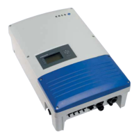
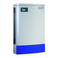
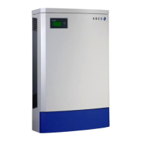
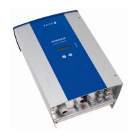
Details the system layout, components, design, and electrical functions.
Details fault signal relay, country-specific functions, and power limitation.
Explains frequency-based power reduction as per BDEW Medium Voltage Directive.
Describes the self-test procedure for grid connection compliance.
Details the DC disconnect and its operation for service.
Lists available interfaces (RS485, Ethernet, USB, SO) for communication and monitoring.
Provides detailed electrical specifications for input and output levels, and general data.
Details physical specifications including display, controls, interfaces, and housing.
Table of grid voltage, frequency, and switch-on times for various countries.
Information on scope of delivery and checking for transport damage.
Safety warnings and instructions for safely transporting the inverter.
Requirements for the installation location, including climate and accessibility.
Criteria for wall mounting, including load capacity and material.
Steps to open the connection area for electrical connections.
Guidance on conductor cross-sections for AC and DC connections.
Details on conductor cross-sections and fuse protection for grid connection.
Step-by-step instructions for making the AC grid connection.
Instructions for connecting the DC positive and negative plugs.
Procedure for checking for ground faults before connecting the DC generator.
Details on maximum input power and its relation to input voltage.
Guidance on applying equal MPP voltages to inputs for standard connection.
Instructions for connecting DC inputs in parallel, noting string voltage requirements.
Important notice regarding short-circuiting unused MPP trackers.
Steps to connect the PV generator and ensure IP54 rating.
Optional procedure for grounding the inverter housing.
Information on connecting interfaces located behind the connection cover.
Wiring diagram and connection details for the RS485 interface.
Information on connecting the optional remote control line for the power supply company.
How to connect the SO pulse output for accessories like displays.
Instructions for connecting the Ethernet interface, including cable type and length.
Steps to connect the inverter to the network and configure settings.
Instructions for connecting the fault signal relay contact.
Procedure to seal the connection area after installation.
Safety warnings and steps for initial start-up of the inverter.
Overview of the inverter's control panel, LCD, and status LEDs.
Explanation of the different operating states indicated by the LEDs.
Detailed table of operating states, LEDs, display, and descriptions.
Description of the graphical display, its functions, and data presentation.
Instructions on how to operate the inverter using the control keys.
Guide through the configuration assistant for initial inverter setup.
Overview of the main menu and its structure on the LCD.
Detailed table of menu items, settings, and their corresponding actions.
How to display recorded operating data graphically for a specific day.
How to display recorded operating data graphically for a specific month.
How to display recorded operating data graphically for a specific year.
Procedure for exporting saved operating data to a USB storage device.
How to select the desired language for the user interface.
Setting the total yield to a selectable value, e.g., after unit replacement.
Configuration for RS485 bus address and termination.
Setting the pulse rate for the SO connection.
Enabling the fault signal relay for home feed-in function.
Defining switch-on power and operating time for Relay 33.
Reducing waiting times during self-test by pressing the 'Activate' key.
Setting the time between two log data recordings.
Activating or deactivating log data backup to a USB storage device.
Configuring display contrast and backlight timeout.
Setting the correct time and date for accurate logging.
Assigning IP address, subnet mask, and gateway for the Ethernet interface.
Activating or deactivating the integrated web server for monitoring.
Instructions to display the hidden 'Parameters' menu.
Setting the country for country-specific operating parameters.
Selecting the applicable grid type and guideline for the inverter.
Configuring voltage thresholds for inverter shutdown.
Setting voltage thresholds for grid shutdown based on EN 50160.
Specifying the voltage drop threshold for grid shutdown.
Setting frequency limits for inverter shutdown.
Setting the starting voltage for feed-in.
Deactivating MPP seek mode for constant DC voltage operation.
Setting the switch-off threshold for overvoltage shutdown.
Setting switch-off thresholds for fast and slow undervoltage shutdown.
Activating or deactivating dynamic grid stabilization (Fault Ride-Through).
Configuring power factor and idle power settings.
Selecting the type of phase shift for power factor settings.
Setting the idle power Q (in%) to a fixed value.
Defining support points for the idle power characteristic curve.
Defining how many support points can be set in the characteristic curve menu.
Setting the power factor for the first support point.
Setting the power factor for the second support point.
Specifying the target voltage and slope for the Q(U) curve.
Manually starting the self-test procedure.
Methods for monitoring inverter operating state and yield data.
Instructions for using the USB interface to read saved operating data.
Steps to connect a USB device and read log data from the inverter.
Information about the integrated web server for remote monitoring.
Steps to configure Ethernet interface for web server access.
How to call up and use the web server for monitoring data.
Choosing the time frame (day, month, year, overall) for displaying yield data.
How to show or hide specific measured values in the day view.
Guide for updating the inverter's software using a USB stick.
Instructions for inspecting the inverter and leads for visible damage.
Safety warnings and procedures for cleaning the inverter's exterior.
Safety precautions and steps for shutting down the inverter for maintenance.
Sequence for safely shutting down the inverter before maintenance.
General procedure for handling faults and notifying authorities.
Safety warnings and general steps when a fault occurs.
Table listing faults, causes, explanations, and remedies.
Overview of display messages and the function of the 'Fault' LED.
Shows how fault and status messages are displayed on the inverter.
Table detailing operating states, display messages, explanations, and actions.
Contact information for technical problem resolution and consultation.
Safety warnings and sequence for shutting down the inverter.
Steps for removing the inverter from its installation.
Procedure for dismantling the inverter for further use or disposal.
Instructions for proper disposal of the inverter unit.
Guidance on proper disposal of the transport packaging.
Confirms compliance with EU directives and standards, includes CE marking.
Confirms compliance with low-voltage grid connection guidelines and standards.
Safety certificate details and testing bases for the inverter.
Table of input power values based on DC voltage for different models.
Examples of valid and invalid DC input connections.
Table illustrating invalid switching states for DC input connections.