L
Kalmar Industries
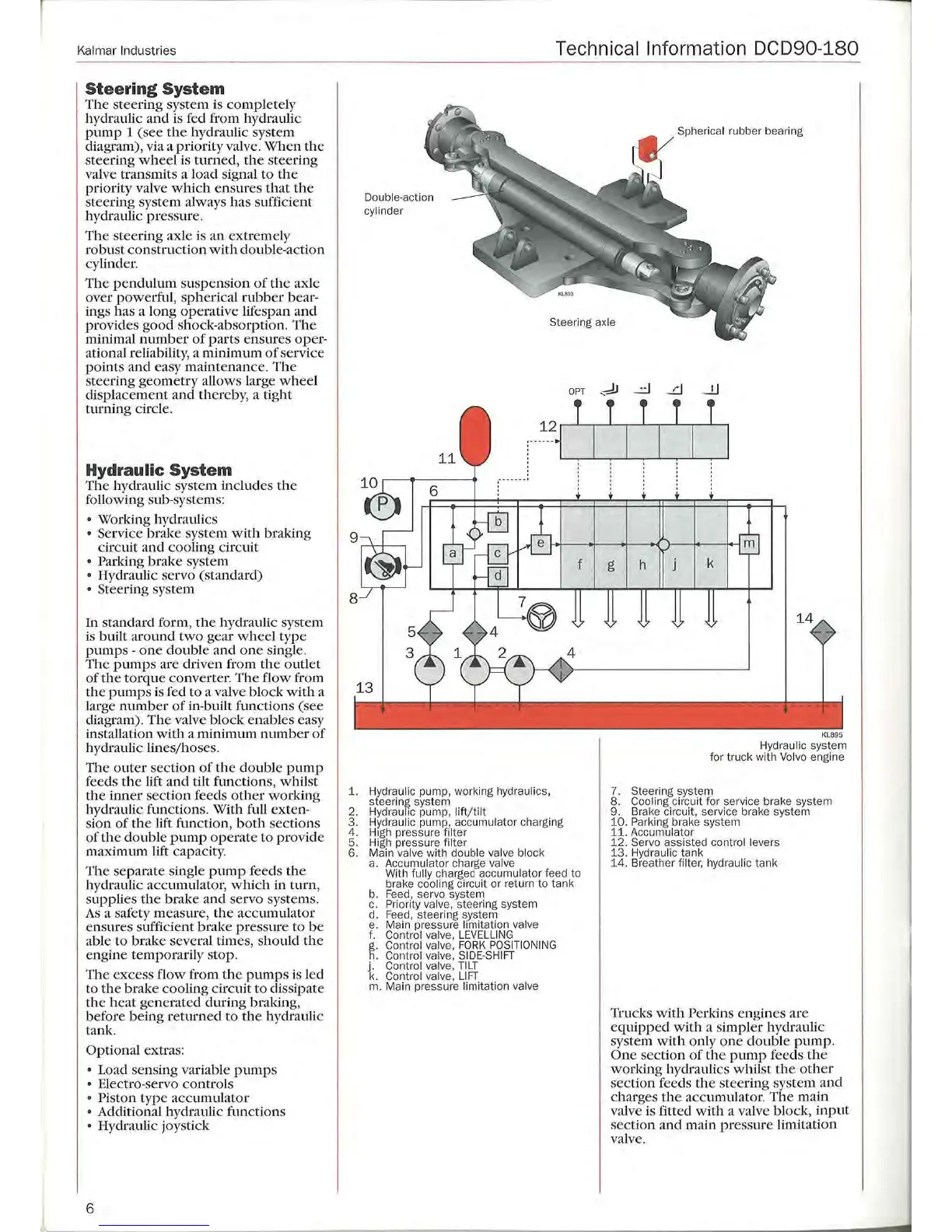
Steering System
The steering system is
co
mpl
etely
hydraulic
and
is
ted
from hydraulic
pump
1 (see
th
e hydraulic system
diagram), via a priority valve.
Wh
en the
st
ee
ring
whee
l is
turned
,
th
e st
ee
ring
v
al
ve transmits a load signal to the
priority val
ve
which
ensures
that
the
st
ee
ring system always has sufficient
hydraulic
pr
ess
ur
e.
Th
e steering
ax
le
is
an
extremely
robust
co
nstruction with double-ac
ti
on
cylinder.
Th
e p endulum suspension
of
the
ax
le
over powerful,
spherica
l
rubber
bear
-
ings has a lo
ng
operative lif
espan
and
pro
vides good s
ho
ck-absorption .
The
minimal
numb
er of parts ensures
oper
-
ational reliability, a minimum
of
se
rvice
point
s and easy ma
int
enance. The
st
ee
ring
geometry
allows large
whe
el
displa
ce
me
nt
and
thereb
y,
a tig
ht
tmning
circle.
Hydraulic System
Th
e hydraulic system includ
es
th
e
following sub-systems:
• Working hydrauli
cs
• Service bral{e system
with
br
aking
circuit and cooling circuit
• Parking brake sys
tem
• Hydraulic servo (standard)
• St
ee
rin
g system
In standard form,
the
hydraulic system
is built a
round
two
gear
wheel
type
pump
s -
one
double and
one
single.
Th
e
pumps
are driven from
th
e o utlet
of
the
to
rque
converter.
The
fl
ow
from
th
e
pumps
is
feel
to a
va
lve block
with
a
large
number
of
in-built fun
ct
ions (see
diagram). The valve block enabl
es
easy
installation
with
a minimum
number
of
hydraulic lin
es/
ho
ses.
The
oute
r section
of
th
e
do
uble
pump
feeds
the
lift
and
tilt functions,
wh
il
st
the
inner
sect
i
on
feeds
other
working
hydraulic function
s.
With fu
ll
exten-
sion
of
th
e lift function, both
sec
tions
of
the
double
pump
operate
to
pr
ovide
maximum
lift
ca
pa
city.
The
separate single
pump
f
ee
ds
the
hydraulic accumulator,
which
in
turn
,
suppli
es
th
e brake
and
servo systems.
As
a safety meas
ur
e,
the
accumu
lator
ensures suffici
ent
brake pressure
to
be
able to
br
ake several times, should
th
e
engine temporarily stop.
Th
e excess
flow
from
the
pump
s is l
ed
to
th
e brake cooling circ uit to dissipate
the he
at
generated during braking,
befo
re
being re
turned
to
the
hydraulic
tank.
Optional extras:
• Load sensing variable
pump
s
• Electro-servo
co
ntrols
• Piston
type
accumul
ator
• Additional hydraulic functions
• Hydraulic joystick
6
Technical Information DCD90-180
Double-action
cyl
in
de
r
Spherical
rubber bearing
Steering
axle
1. Hydraulic
pu
mp, working
hyd
raulics,
steering system
2.
H
yd
raulic pump,
lift/t
ilt
3. Hydraulic pump, accumulator charging
4.
H1
gh
pressure filter
5. High press
ur
e fil
te
r
6. Main valve wi
th
double
va
l
ve
block
a.
Accumulator
cha
r
ge
valve
With fully charged accumulator feed to
brake
cooling circuit or return to tank
b.
Feed,
servo system
c.
Priority valve, steering syst
em
d.
Feed,
steering system
e.
Main pressure limitation
va
l
ve
f. Contr
ol
valve,
LEVELLING
g .. Contr
ol
valve,
FORK
POSITIONING
h
Co
ntr
ol
valve,
SIDE
-
SHIFT
j.
Control valve,
TILT
k. Contr
ol
valve,
Ll
FT
m. Main pressure limitation valve
KL695
Hydra
ulic system
fo
r tru
ck
with
Vo
l
vo
engine
7. Steering system
8.
Cooling
ci
rc
uit for
se
rvi
ce
brake system
9. Brake
ci
rcuit, service brake system
10
.
Pa
rking brake system
11
. Accumulator
12.
Se
r
vo
assisted control levers
13.
Hyd
raulic tank
14.
Breather filter, hydraulic tank
Trucks
with
Perkins engines
are
equipped
with a simpl
er
hydr
aulic
system
with
on
ly
one
double
pump.
One
section
of
th
e
pump
feeds
the
working hydrauli
cs
whi
l
st
the
other
sect
ion
f
ee
ds
the
steer
ing system a
nd
charges
the
accumulator.
The
main
va
lve is fitted
with
a valve block,
input
section and main
pr
ess
ur
e limitation
va
lve.
--
 Loading...