t the time of writing this manual (April 1998) there is no
wareness of any field based situation where such
nterference has ever occurred and this advice is only given
o satisfy the requirements of the Directive.
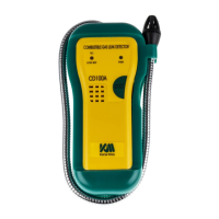
Sensor Filter and Sensor Replacement
he sensor is housed at the tip of the gooseneck assembly.
. Pull off the top half of the sensor housing. Pushing to
one side aids removal.
. With care move the ‘Tip-light’ LED to one side to
gain access to the sensor (small silver can).
. Unplug the sensor and replace it with a new one.
ote: The sensor can be fitted in either one of two ways
ithout affecting instrument operation.
. Realign the LED ensuring it sits above the sensor.
. Replace sensor cover by pushing it firmly in place.
Note ! the locating pin between the body and sensor
cap.
he sensor has a life greater than 3 years.
Downloaded from Elcodis.com electronic components distributor