EasyManua.ls Logo

Kantronics KPC-3+ - User Manual

Default Icon
2 pages
Print Icon
To Next Page IconTo Next Page
Loading...
4/05 ©2005 Kantronics Inc.
Kantronics KPC-3+ Port Pinout Information
KPC-3+ Rear View
Radio Port (DB-9) Pin-out:
Pin no. Signal name Function Related Jumpers
1 TXA Transmit audio (AFSK out) J9
2XCD
External carrier detect (transmit inhibit) input
or (via software command w/ 8.2 or higher firmware
version) alternate GPS Input port
Software Command
3 PTT Push-to-talk (to radio PTT/transmitter enable input)
4 CTRLB/AN0 Control line B (or AN0 input) J8
5 RXA Receive audio (AKSK in) J3, J4
6 GND Ground
7 EXT-IN External input for Power/Reset J6, J7
8 CTRLA /AN1 Control line A (or AN1 input) J10
9 GND / RESET Ground or Reset Input (jumper selectable – J5) J5
To find corresponding pin-outs for many radios, visit www.packetradio.com.
Port-Related Jumpers
J3: Input Impedance Select
1 2
RXA input impedance 10 k
. (default)
1 2
RXA input impedance 600
.
J4: Radio Port Pin 9 Function Select
1 2
Input Equalization on.
1 2
Input Equalization off. (default)
J5: Radio Port Pin 9 Function Select
1 CTR 2
Radio Port pin 9 is ground. (default)
1
CTR 2
Radio Port pin 9 is external reset input.
Radio Port
Computer or GPS Port
Question and Answer IconNeed help?

Do you have a question about the Kantronics KPC-3+ and is the answer not in the manual?

Overview

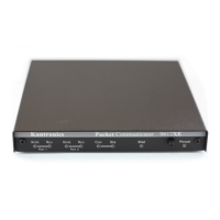
The Kantronics KPC-3+ is a versatile packet radio controller, designed to facilitate data communication between computers, GPS devices, and radio transceivers. It serves as a crucial interface for amateur radio enthusiasts and professionals engaging in packet radio operations.

Function Description

The KPC-3+ acts as a Terminal Node Controller (TNC), enabling digital data transmission over radio frequencies. It translates data from a computer or GPS device into a format suitable for radio transmission (AFSK out) and converts incoming radio signals (AKSK in) back into data that a computer can understand. This bidirectional communication is fundamental to packet radio, allowing for applications such as digital messaging, telemetry, and position reporting.

The device features two primary ports: a Radio Port (DB-9 female) and a Computer/GPS Port (DB-25 female). The Radio Port handles audio input/output and control signals for the radio, while the Computer/GPS Port manages data transfer and control signals for the connected computer or GPS unit.

Key functions include:

  • Transmit Audio (TXA): Outputs AFSK (Audio Frequency Shift Keying) modulated audio to the radio for transmission.
  • Receive Audio (RXA): Accepts AFSK modulated audio from the radio for demodulation.
  • External Carrier Detect (XCD): An input that can inhibit transmission, or, with specific firmware (v8.2 or higher), serve as an alternate GPS input.
  • Push-to-Talk (PTT): Activates the radio's transmitter.
  • Control Lines (CTRLA/AN1, CTRLB/ANO): General-purpose control inputs, also configurable as analog input channels.
  • Ground (GND): Provides a common electrical reference.
  • External Input (EXT-IN): Configurable for power or reset functions.
  • Reset Input (GND/RESET): Allows for external reset of the device, or can be configured as a ground.

The Computer/GPS Port facilitates data exchange with a host device:

  • Transmit Data (TXD): Sends data from the computer/GPS to the KPC-3+.
  • Receive Data (RXD): Sends data from the KPC-3+ to the computer.
  • Request to Send (RTS): A hardware flow control signal from the computer, indicating its readiness to receive data.
  • Clear to Send (CTS): A hardware flow control signal from the KPC-3+, indicating its readiness to receive data.
  • Data Set Ready (DSR): Indicates that the KPC-3+ is powered up.
  • Data Carrier Detect (DCD): Signals the status of the current I/O stream, indicating whether the KPC-3+ is connected to another packet station.
  • Data Terminal Ready (DTR): Indicates when the computer's port is active (currently ignored by the KPC-3+).
  • Frame Ground (FG) and Signal Ground (SG): Provide safety and signal reference grounds, respectively.

Important Technical Specifications

The KPC-3+ utilizes various jumpers for configuration, allowing customization of its behavior to suit different operational needs. These jumpers control aspects such as input impedance, port functionality, and external input behavior.

Radio Port (DB-9) Specifications:

  • RXA Input Impedance: Selectable between 10 kΩ (default) and 600 Ω via J3. This allows matching the input to different radio audio output characteristics.
  • Pin 9 Functionality: Configurable via J5 to be either a ground (default) or an external reset input.
  • Control Line B (CTRLB/ANO) / Analog Input 0: J8 selects whether this pin connects to Radio Port pin 4 or Computer Port pin 18.
  • Control Line A (CTRLA/AN1) / Analog Input 1: J10 selects whether this pin connects to Radio Port pin 8 or Computer Port pin 11.
  • AFSK Output Line (J9): Configurable for "Normal" base station use (default) or to also serve as PTT for HT (handheld transceiver) radios.

Computer/GPS Port (DB-25) Specifications:

  • Pin 13 (None / EXT-IN): This pin can be configured via J6 and J7 to be an external reset input, external power input, or not connected (default). It can also be routed to either Computer Port pin 13 (J7) or Radio Port pin 7 (J7).
  • Pin 11 (None / AN1): Configurable as Analog Input channel 1, linked to J10.
  • Pin 18 (None / ANO): Configurable as Analog Input channel 0, linked to J8.

Usage Features

The KPC-3+ offers significant flexibility through its jumper-selectable configurations, making it adaptable to a wide range of packet radio setups.

  • Versatile Connectivity: Supports connection to various radios (via DB-9) and computers/GPS devices (via DB-25), accommodating different hardware ecosystems.
  • Hardware Flow Control: Utilizes RTS/CTS signals on the Computer/GPS port for reliable data transfer, preventing buffer overflows and ensuring data integrity.
  • Analog Input Capabilities: The CTRLA/AN1 and CTRLB/ANO lines can function as analog inputs, potentially allowing for telemetry applications where analog sensor data is transmitted.
  • External Control Options: The EXT-IN and GND/RESET pins provide options for external power, reset, or other control functions, enhancing system integration.
  • Firmware Upgradeability: The mention of firmware version 8.2 or higher for alternate GPS input on XCD suggests that the device's capabilities can be expanded or modified through software updates.
  • Radio Compatibility: The ability to select RXA input impedance (10 kΩ or 600 Ω) and configure the AFSK output line for HT radios demonstrates its compatibility with a broad spectrum of radio equipment.

Maintenance Features

While the document does not explicitly detail maintenance procedures, several aspects can be inferred:

  • Jumper Configuration: The extensive use of jumpers for configuration implies that initial setup and any subsequent changes to the device's behavior are performed by physically adjusting these jumpers. This requires opening the device casing.
  • Firmware Updates: The reference to specific firmware versions suggests that firmware updates might be available to enhance functionality or fix issues. The method for performing these updates is not described but would typically involve a connection to a computer.
  • Shielding: The note "All cables must be well shielded" is a critical maintenance and installation instruction, emphasizing the importance of proper cabling to prevent electromagnetic interference (EMI) and ensure reliable operation.
  • Protection against Damage: The warning "To prevent damage to your PC or other external device, make sure that the jumpers controlling the use of pin 13 of this port are in their factory default 'none' position if you are not using a cable specifically wired for external power / external reset applications" highlights a key protective measure. Users must be careful when configuring pin 13 to avoid potential damage to connected equipment.
  • Troubleshooting: The signal names and their functions, along with the related jumpers, provide a comprehensive guide for troubleshooting connectivity and operational issues. For example, if the KPC-3+ isn't receiving data, checking the DCD signal and RXD line, and ensuring correct RXA impedance (J3) would be initial steps.

The Kantronics KPC-3+ is a robust and configurable device, designed to be a reliable component in various packet radio communication systems, offering both essential functionality and adaptability through its detailed jumper settings.

Kantronics KPC-3+ Specifications

General IconGeneral
BrandKantronics
ModelKPC-3+
CategoryController
LanguageEnglish

Related product manuals