Parameter setting and the way to check the ESC real time data
The ESC parameters can be programmed to meet dierent ight needs.
The ESC real time data like current, voltage, ESC temperature, throttle, and
ESC status code can be checked by LCD program card or Mobile phone APP.
(LCD Programming Card and/or Bluetooth module needs to be purchased
separately.)
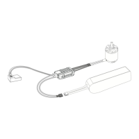
ESC
Battery
Programming Card
B: Operating steps
1. Connect the ESC to LCD program card and battery co-
rrectly base on above wire connection diagram.
(The LCD program card connecting wire:Red wire co-
rresponds to the “+” and Black wire correspond to the
“-” position, pay attention to the “+” “-” lettering on the
LCD and ESC) .
2. After connected well, LCD program card turns on and
will go to the real time data interface rst.
(Real time data includes: voltage/current/throttle/RPM/
temperature and so on)
3. Then press “ITEM” or “OK” button, it goes to the para-
meters setting interface.
(In parameters setting interface, press“ITEM” to change
the programmable items, press “
or
button to
choose the item parameters, and press “OK” to save
settings.)
4. After set the new ESC parameters, need to re-power the
ESC again, then the new set parameters will take eect.
1. Programmable parameter items and corresponds programmable set values
Parameter Value
1. Gov Mode *ESC-StoGov Ext-Gov
2. Low Voltage Cuto
Threshold
OFF 2.7V *3.0V 3.2V 3.4V 3.6V 3.8V
3. Timing *Auto Low Middle High
4. BEC 6V 7.4V *8.4V
5. Motor Rotation *CW CCW
6. Governor Parameter P 1 2 3 *4 5 6 7 8 9 10
7. Governor Parameter I 1 2 *3 4 5 6 7 8 9 10
8. Acceleration Fast Normal *Slow Very Slow
9. Auto Restart Time *O 90s(ON)
10. Helicopter Model Other OMP-M4
*OMP-
-M4MAX
11. Restore Factory
Setup Defaults
Restore Factory Setup Defaults
Note: "*" values are default settings
Normal startup procedure
1. Turn on the transmitter, move the throttle stick to the bottom position.
2. Connect the battery pack to the ESC and wait for about 2 seconds.
3. The motor will beep several sounds, sounds time presents the amount of
battery cells.
4. When the motor emits ”Beep----Beep”, means self-test is nished, the ESC
is ready to work.
1. Using LCD program card to set the ESC parameters
A. Wire connection diagram
Programmable parameters items and instructions
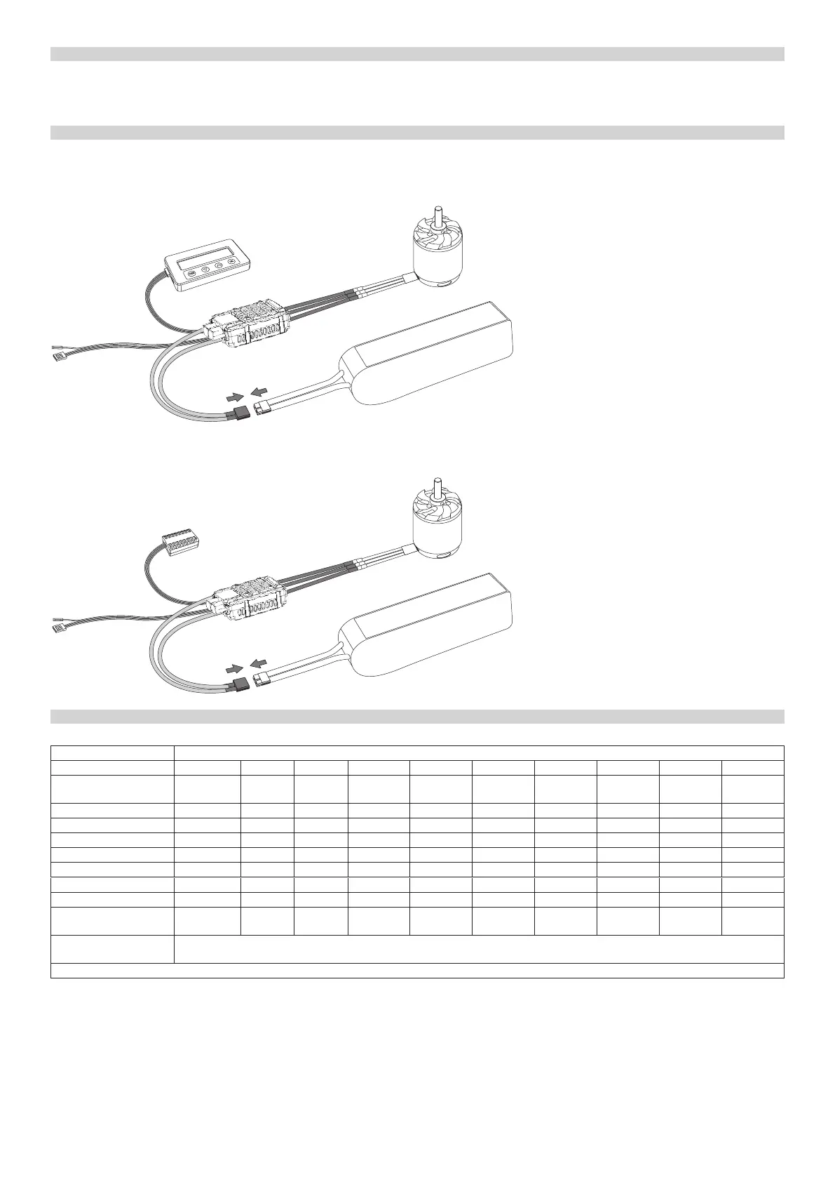
ESC
Battery
Bluetooth Module
B: Operating steps
1. Connect the ESC to the Bluetooth module and battery
correctly base on above wire connection diagram.
(Blue tooth module Red wire corresponds to “+” and
Black wire corresponds to “-”, pay attention to the “+”
and “-” lettering on the ESC)
2. Download and install the APP well, open APP and co-
nnect it with Bluetooth, then you can start to set the
ESC parameters and check the real time data by APP.
3. After set the new ESC parameters, need to re-power the
ESC, then the new set parameters will take eect.
2. Using Mobile phone APP to set the ESC parameters and view real time data
A. Wire connection diagram
2. Programmable parameter project description
1. Gov Mode:
EXT-Gov/ESC StoGov, default setting is ESC StoGov.
2. Low Voltage Cuto Threshold
2.7V/3.0V/3.2V/3.4V/3.6V/3.8V adjustable,default setting is 3.0V.
(Note:the voltage means each cell voltage. For example if you used 6 cells
Lipo battery, then the low voltage threshold value is 6x set voltage value).
3. Timing
Adjust the angle of the motor electrically. Auto/Low/Middle/High adjustab-
le, default setting is Auto.
4. BEC
6.0V/7.4V /8.4V adjustable, default setting is 8.4V.
5. Motor Rotation
CW/CCW adjustable, default setting is CW.
6 Governor Parameter P
Control the degree of rotation while maintaining at xed speed. The higher
the value, the greater the degree of regression target speed when the speed
is insucient. Whereas, when the speed is too high, the function needs to
be combined with the xed speed sensitivity I setting. 1 to 10 adjustable,
default setting is 4.
 Loading...