7. Governor Parameter I
When the speed fails below, or exceeds the value set, the speed is com-
pensated by the ESC. This parameter is used to resize the degree of rotation.
Too large parameters will cause excessive make-up, too small parameters
will cause insucient replacement.1 to 10 adjustable, default setting is 3.
8. Acceleration
The higher value means more soft throttle acceleration.
9. Auto Restart Time
The ESC will cut o its output when the throttle amount is between 15%-
30%, if you increase the throttle amount to above 30% within preset time
period (0-90s), the motor will rapidly start up and accelerate to the speed
corresponds to the specic throttle amount, complete the shutdown and
restart up. If you move the throttle stick to over 30% beyond the preset time
period, the ESC will enter the soft start-up process.(Note: This function won‘t
take eect if the throttle amount is less than 15%).
10. Helicopter Model
When selecting the M4 / M4MAX corresponding models, there is no need to
calibrate the speed controller for constant speed control. For other options,
the speed controller needs to calibrate the speed for the rst time when ena-
bling constant speed control,default setting is MAX.
11. Restore Factory Setup Defaults
Restore Factory Setup Defaults.
The Fixed Speed Function Settings
1. Fixed speed description
By speed calibration, the motor speed-throttle value corresponding curve is
established. The throttle value is set to a xed value on the remote control,
the output of the throttle value corresponds to the speed, and the motor
load changes to maintain the same speed.
2. Speed calibration process
1. Need to do the throttle calibration rst before the speed calibration (if al-
ready done, just skip this step).
2. Make sure the main rotor pitch is at 0 degrees.
3. Pull the throttle stick to the minimum position, waiting for the esc self-
-check process.
4. Push the throttle to 50%, the rotor of the helicopter will start to slowly
accelerate (the main rotor pitch is zero degrees, the helicopter will not lift
o,) and wait for the acceleration to complete, When the rotor speed is
stable, push the throttle stick to the minimal position.
5. Speed calibration is nished.
6. If it is M4/M4MAX, calibration is not required, and you can directly choose
the helicopter type. For other helicopters, you need to rst select „Other“
and then proceed with calibration.
3. How to calculate the main rotor RPM at 100% throttle
1. Connect the LCD program card or Bluetooth after the speed calibration is
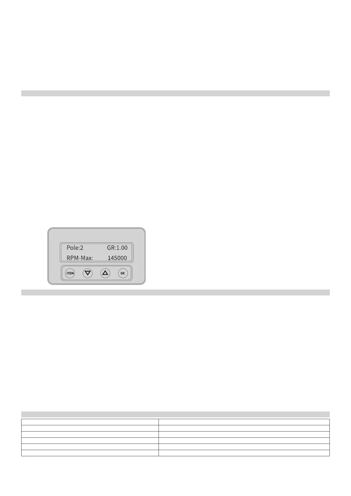
completed to nd the records as shown:
The values in the gure is just a example, depending on the actual dis-
play values. This value is the maximum electrical speed that the motor can
achieve at 100% throttle.
2. For example, if motor have 10 poles, using 13 motor teeth with main teeth
of 120T, the gear ratio is around 9.23.
And Formula:
100% throttle speed of the main rotor= MAX RPM/[(motor poles/2) x gear ratio]
Then the main rotor 100% throttle speed is 145000 / [(10/2) x (120/13)] is
around 3410RPM.
If the main rotor during 3D ight requires to be maintained at 2500 rpm,
the xed speed throttle needs to be set at 2500/3410 to get about 0.8. At
0.8, the throttle value needs to be set at 80%.
3. You can set motor poles and the gear ratio (GR) on a LCD program card to
get the speed of the main rotor at 100% throttle.
(1) Connect the ESC to a LCD program card after the speed is calibrated,
and then enter the interface as shown above.
(2) Press “OK” to select options related to “motor poles” , press “OK” to se-
lect gear ratio (GR) by , then press “OK” will show the speed of the main
rotor at 100% throttle.
Protection Function
1. Abnormal power-on voltage protection: The ESC enters a protective state
once the input voltage detected is not in the operating voltage, Promp-
ting LED light to ash.
2. Start-up protection: If the motor fails to start normally within 2 seconds af-
ter pushing the throttle to start, the ESC will cut o the output power, and
you need to make the throttle calibration again, then ESC can be restar-
ted. Possible reasons: disconnection or poor connection between ESC and
motor, the propeller or motor is blocked by other objects, the gearbox is
damaged, etc.
3. Over-heat protection: When the temperature of the ESC is over about
110°C, the ESC will automatically reduce the output power for protection,
but will not fully shut down the power, reduce it to 70% of the full power at
most to ensure the motor has enough power to avoid crashes.
4. Throttle signal loss protection: The ESC will reduce the output power if
throttle signal is lost for 1 second, will cut o output to the motor if the
throttle signal is lost over 2 seconds. If the throttle signal restored during
power down, the ESC will immediately restored throttle control. In this
way, the ESC will not protect when the signal loss less than 2 seconds, only
when the signal lost is over 2 seconds or longer time. And the ESC will
reduce the output power gradually instead of cutting o it immediately,
so the player has enough of time to save the plane, taking into account
safety and practicality.
5. Over load protection: The ESC will cut o power or restart automatica-
lly when the load increased a lot suddenly, possible reason is the motor
blocked.
6. Low voltage protection: When the operating voltage of the ESC have ex-
ceeded the protection voltage set, power will be gradually reduced for
safety, but will not be turned o, These will still be up to 50% of power,
to ensure that the motor has the power to land.
7. Over-current protection: When the peak current exceeds the specied va-
lue, the ESC will immediately cut o the output power, and then restart
to restore the power. If the current exceeds the specied value again, the
output power will be completely cut o. Possible reason is overload, burnt
motor and so on.
8.Break protection: If there is a break in the connection between the motor
and ESC. Check the motor is fully connected,check connectors or solder
joints are as they should be.
Explanations for Warning Tones
Troubles Warning Tones
1. Throttle signal loss “Beep--Beep--” (every two seconds)
2. Temperature protection “Beep Beep-Beep Beep--” (every two seconds)
3. Low voltage protection “Beep Beep Beep--Beep Beep Beep--” (every two seconds)
4. The throttle value is not at 0% throttle on the power-up “Beep-Beep-” (every 0.2 seconds)
5. The voltage is not within the range “DoReMi-DoReMi-” (every 0.2 seconds)
 Loading...