This document serves as the Owner's & Installation Manual for Kaysun Floor Standing Units, specifically covering models KSEF-22 DN5.0, KSEF-36 DN5.0, KSEF-56 DN5.0, and KSEF-80 DN5.0. It provides comprehensive information for the installation, operation, maintenance, and troubleshooting of these air conditioning units.
Function Description:
The Kaysun Floor Standing Units are air conditioning systems designed to provide comfort in various indoor environments. They are capable of both cooling and heating, with specific models being heat pump types. The units utilize a refrigerant system, with R32 refrigerant mentioned for certain models, requiring specific safety precautions due to its flammability. The system includes an indoor unit (IDU) and an outdoor unit (ODU), which communicate to regulate room temperature and airflow. Optional accessories such as wired controllers, remote controllers, and display boxes are available to enhance control and user interaction.
Important Technical Specifications:
The manual provides electrical specifications for the IDU, including unit power (kW), frequency (Hz), voltage (V), Minimum Circuit Amps (MCA), Maximum Fuse Amps (MFA), and Indoor Fan Motor (IFM) power input (W).
- Unit Power (kW): 2.2, 3.6, 5.6, 8.0
- Frequency (Hz): 50
- Voltage (V): 220~240
- MCA (A): 0.3 (for 2.2kW and 3.6kW), 0.4 (for 5.6kW and 8.0kW)
- MFA (A): 15 (for all listed kW models)
- IFM power input (W): 100 (for all listed kW models)
- IFM power input (W) (second column): 0.50 (for 2.2kW and 3.6kW), 0.60 (for 5.6kW and 8.0kW)
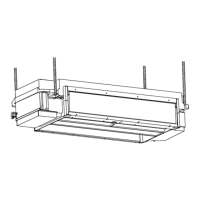
Dimensions are provided for different capacities:
- 2.2kW & 3.6kW: A=1020mm, B=495mm, C=764mm, D=375mm, E (Liquid side) = 6.4mm, F (Gas side) = 12.7mm, G=915mm, H=470mm.
- 5.6kW & 8.0kW: A=1360mm, B=591mm, C=1104mm, D=391mm, E (Liquid side) = 6.4mm (5.6kW) / 9.5mm (8.0kW), F (Gas side) = 12.7mm (5.6kW) / 15.9mm (8.0kW), G=1253mm, H=566mm.
Refrigerant piping specifications include:
- Copper pipe (Unit: mm):
- kW≤5.6: Liquid side Φ6.35×0.75, Gas side Φ12.7×0.75
- 5.6<kW≤16.0: Liquid side Φ9.52×0.75, Gas side Φ15.9×1.0
- Thermal insulation pipe thickness: Usually 10mm or above for copper pipe, 15mm or above for rigid polyethylene plastic tube. Increased thickness for closed humid areas.
- PVC water discharge pipe: 18mm diameter.
Communication line diameter selection varies based on the communication method and power supply:
- HyperLink (M1M2) with independent power supply: 2 x 1.5mm² wire, resistance ≤ 1.332/100m, length ≤ 600m (add two repeaters).
- HyperLink (M1M2) with uniform power supply: 2 x 0.75mm² (shielded cable), length ≤ 2000m.
- P/Q communication: 2 x 0.75mm² (shielded cable), length ≤ 1200m.
- P/Q/E communication: 3 x 0.75mm² (shielded cable), length ≤ 1200m.
- X1X2 communication: 2 x 0.75mm² (shielded cable), length ≤ 200m.
- D1D2 communication: 2 x 0.75mm² (shielded cable), length ≤ 1200m.
Usage Features:
- Operating Range: The IDU operates stably within an indoor temperature range of 16~32°C for cooling (with humidity ≤80%) and 15~30°C for heating.
- Display Box (Optional): Provides visual feedback on unit status. In Standby mode, it displays "---". In Cooling/Heating mode, it shows the set temperature. In Fan mode, it displays indoor temperature. In Dry mode, it shows set temperature and humidity (if set on wired controller). It also displays error codes or special mode running codes.
- Wired Controller: Used for setting parameters, including external static pressure (ESP) for constant speed mode units. The ESP can be adjusted from Level 02 (0 Pa) to Level 10 (60 Pa) depending on the unit power.
- Safety Protections: Includes anti-cold air protection in heating mode (indoor fan temporarily shuts off or runs in Low mode until heat exchanger warms up), and automatic defrosting mode when the outdoor unit frosts.
- Communication: Supports HyperLink (M1M2), RS-485 (PQ), and RS-485 (PQE) communication methods, allowing for various system configurations (independent or uniform power supply, serial, tree, star, or ring topology).
- Error Codes: A comprehensive list of error codes (e.g., A01 for Emergency stop, C21 for abnormal IDU-ODU communication, E24 for T1 sensor fault) and operating status codes (e.g., d0 for oil return, dC for self-cleaning) are provided for troubleshooting.
Maintenance Features:
- Regular Cleaning: Air filters should be cleaned frequently, ideally once a month for units in dusty environments or when prompted by the wired controller. If heavily soiled, filters can be cleaned with a soft brush and neutral detergent.
- Filter Removal: The manual details a procedure for removing the filter bracket and pulling out the filter by unscrewing two screws.
- Air Outlet and Exterior Panels: Can be wiped with a dry cloth or cleaned with water and neutral detergent for stubborn stains.
- In-depth Maintenance: Professional technicians should perform in-depth maintenance every 2 to 3 years.
- Preheating: Before the heating season, the ODU master unit should be powered on for at least 4 hours to preheat, ensuring stable operation and optimal refrigeration oil lubrication.
- Long-term Storage: Before putting the air conditioner out of use for a long period, it should be run in fan mode for 4-5 hours to dry completely, preventing mold growth. The main power switch should be turned off, and batteries removed from the remote controller.
- Drain Pan Maintenance: Steps are provided for dismantling the drain pan for cleaning, emphasizing the importance of ensuring no residual water before removal.
- Motor and Wind Wheel Maintenance: Instructions are given for loosening fastening screws and removing the motor and wind wheel assembly.
- Leak Detection: The system should be checked for refrigerant leaks using foam or an instrument after installation and during maintenance.
- Heat Insulation Treatment: Pipes on both liquid and air sides require thermal insulation to prevent condensation, using materials with a heat resistance of 120°C or higher. Joints and cuts must be sealed with glue and electrical tape.