© Copyright 2022 KE2 Therm Solutions, Inc., Washington, Missouri 63090
Q.1.45 October 2022
Page 4
KE2 EvapOEM
Quick Start Guide
IMPORTANT
Steps to Ensure Proper Coil Sensor Location
The coil sensor acts as defrost termination sensor, and must be installed where frost is last to
disappear during defrost to ensure a clear coil.
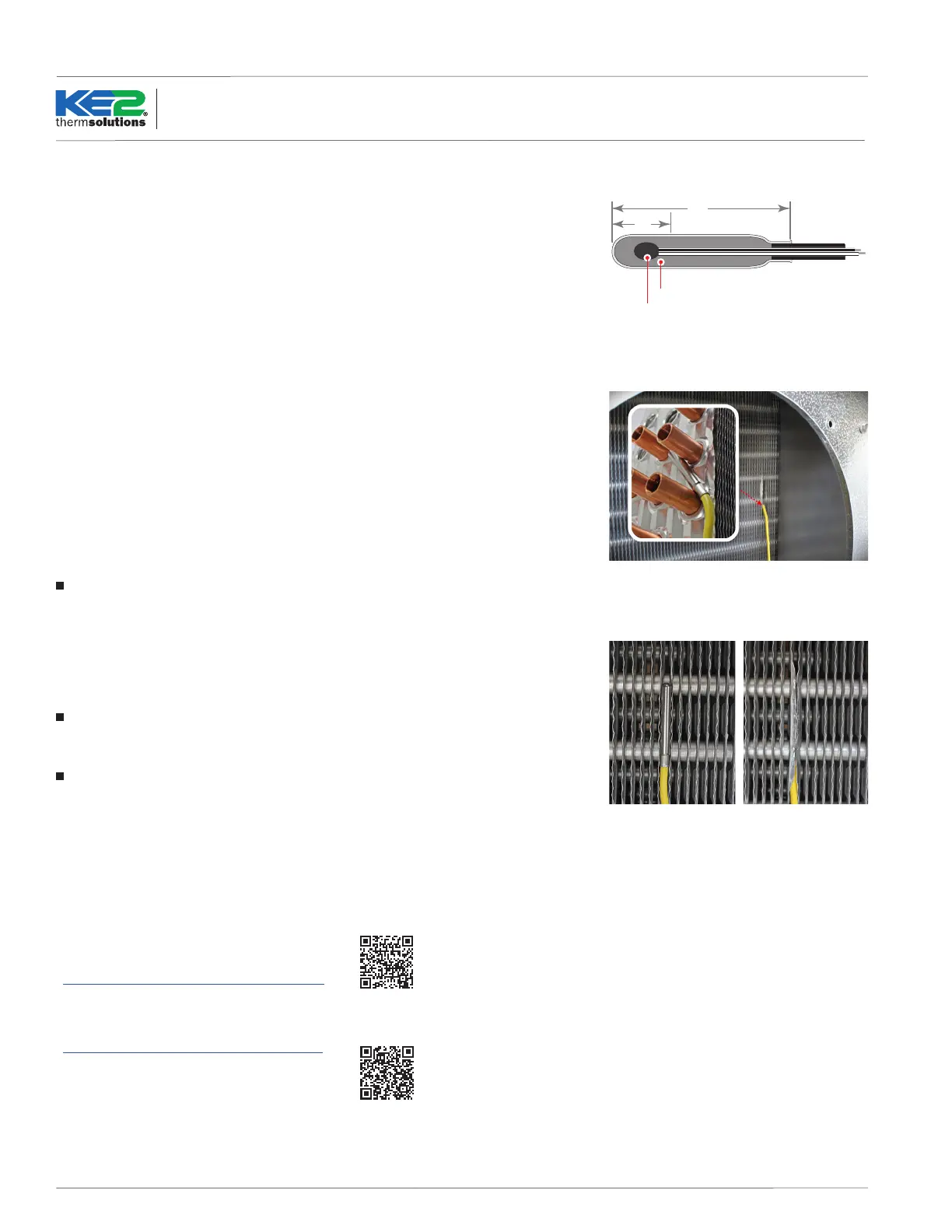
Installing the Sensor - The most active portion of the sensor is the rst 1/2” of the probe.
The photo in Figure 2 shows that the sensor is positioned so that it is touching two circuit tubes.
When inserting the sensor into the coil, the tip should touch one of the circuit tubes, and the probe
should be inserted into the ns so approximately 1/16" of the stainless shielding is still outside of the
ns. Pinch the ns gently together, securing the sensor in place. This provides thermal ballast to ensure
a complete defrost.
NOTE: The sensor should not be located adjacent to the electric heating elements.
Alternate Method - As the defrost termination sensor, it is important to ensure the sensor does not
terminate defrost before all frost is removed from the coil. In some installations, inserting the sensor into
the coil may position it too close to the defrost heat source. An alternate method of positioning, Figure
3a, places the sensor vertically between the coil ns. Figure 3b shows the coil sensor properly secured.
NOTE: On a small fraction of installations the sensor placement may require adjusting. This is
typically caused by product loading, door openings, air ow, high/low superheat etc. The sensor(s)
should be placed where frost disappears last on the coil.
Extending sensor wires
After the sensors are mounted, they are routed back to the controller. If the wires must be extended,
use 18 gauge twisted shielded pair cable. Maximum recommended combined length for extension
is 100 ft.
If additional resistance aects the temperature or pressure reading of the controller, the temperature and
pressure may be “oset” to read correctly. Use the OFFSET* function, in the SETPOINTS menu.
* Requires KE2 Combo Display or access to the KE2 Evap OEM's webpage.
When running the sensor wires to the controller, avoid introducing electrical noise. Electrical noise can
occur when sensor wires are located near high voltage lines. Underwriter’s Laboratories denes high
voltage as above 30V. The higher the voltage, the more likely electrical noise will occur.
If crossing a high voltage line is necessary, run sensor wiring at right angles to prevent noise.
1.5”
Thermistor
Epoxy
.5”
Figure 1
Figure 2
Figure 3a Figure 3b
Technical Videos
Further information on coil sensor placement and installation are available in the videos below:
Determine coil sensor location:
https://www.youtube.com/watch?v=ZZWfEkNK-cE
Properly install a coil sensor:
https://www.youtube.com/watch?v=Q9p3rcjKlAM
 Loading...