hole to assistant fix the tool when laser marking.
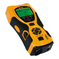
C. LCD with backlight---Indicates detecting or measuring result.
D. Mode switch --- Set the mode for wood joists, AC live wires or metals.
E. +/= ---Addition key: Add the measured length, area or volume
F. Detection button---Press the button to detect when detecting.
G. READ --On/read key: Press this key to start the tool and read the measured distance, keep pressing
this key and move the tool to read dynamic result.
H. RM ---Memory read key: Read out and display the result of length, area or volume which is stored
last time
I. Ultrasonic sensor aperture
J. Laser pointer
K. Function switch--- Select mode for laser mark, distance measure or detection.
L. Level vials
M. M ---Memory input key: Input the length, area or volume into memory
N. Pin button ---Can fix the tool while laser marking.
O. MODE ---Clear/Mode select: Press this key to clear or return back to the menu to select length, area
or volume mode.
ILLUSTRATION OF DISPLAY SCREEN
A. Plus
B. Length/Area/volume (L=length;W=width;H=height)
C. Display when lack of electric quantity
D. Memory
E. Memory, computing result
F. Indication symbol for approaching the target object---the two symbols will light in turn towards the
center symbol when approaching the edge of the detected object.
G. Symbol for central arrow---the light is on when detecting the edge of the detected object.
3
 Loading...