EasyManua.ls Logo

KEENCUT SteelTrak - User Manual

KEENCUT SteelTrak
6 pages
Print Icon
To Next Page IconTo Next Page
Loading...
SteelTrak User Guide –
Maintenance
The world’s finest cutting machines
www.keencut.com
+44 (0) 1536 263158
+1 (716) 748 6203
sales@keencut.co.uk (UK HQ)
sales@keencut.com (US sales)
Scan the QR code or
click here to view this document online >
Page 1 of 6
Question and Answer IconNeed help?

Do you have a question about the KEENCUT SteelTrak and is the answer not in the manual?

Summary

Maintenance

Cleaning and Lubricating

Details cleaning methods for debris and suggests appropriate lubricants like petroleum jelly and light oil for machine parts.

Clamp Maintenance

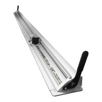
Explains clamp pressure adjustment using grub screws and adjuster bar for even contact on materials.

Guide Wheel Adjustment

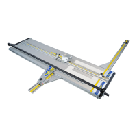
Details adjusting guide wheel tension using a feeler gauge and eccentric shafts to ensure proper fit on rails.

Overview

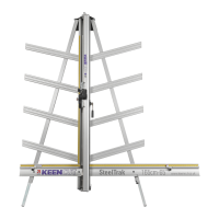
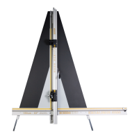
The SteelTrak is a precision cutting machine designed for professional use, manufactured by Keencut, a company specializing in high-quality cutting equipment. This user guide focuses on the maintenance aspects of the SteelTrak, ensuring its longevity and optimal performance.

Function Description:

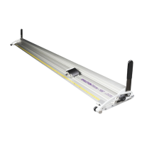
The SteelTrak is engineered to cut a wide range of tough materials with exceptional accuracy and ease. It features a robust design with stainless steel guide rails and a sophisticated clamping system to secure materials during cutting. The machine's cutting head slides smoothly along the guide rails, allowing for precise and consistent cuts. Its primary function is to provide a reliable and accurate cutting solution for various industries, including sign-making, framing, and graphic arts. The design emphasizes minimal maintenance while ensuring high performance.

Important Technical Specifications (Inferred from Maintenance Guide):

  • Guide Rails: Two stainless steel guide rails (1) embedded into the slideway, ensuring smooth and precise movement of the cutting head.
  • Guide Wheels: Four grooved guide wheels run on the rails. Two are fixed (A), and two are adjustable (B). These wheels are factory-adjusted and generally do not require re-adjustment under normal circumstances.
  • Clamping System: Features a moving clamp bar that presses evenly onto the material being cut. The clamp pressure is adjustable via two small grub screws in the housing and an adjuster at the top end of the push rod.
  • Lubrication Points: Specific areas requiring lubrication include guide rods, rollers, ratchet system (pivot point and teeth), balance weight opening, ratchet release bar, and the curved slot on the swinging arm.
  • Feeler Gauge Requirement: A 0.15mm (0.006″) feeler gauge or a stout piece of paper is used to measure the gap under the Spring Block for guide wheel tension adjustment.
  • Wrench Sizes: 10mm wrench for the silver locking nut of the clamp adjuster, 13mm spanner for the locking nut of the guide wheel shaft, and a 5mm spanner (or grips) for the square end of the guide wheel shaft.
  • Thread Types: The silver locking nut of the clamp adjuster has a normal right-handed thread, while the black locking nut has a left-hand thread.

Usage Features:

The SteelTrak is designed for ease of use, even with tough materials. Its clamping system ensures that materials are held firmly and evenly, preventing slippage and ensuring accurate cuts. The cutting head's smooth movement along the guide rails contributes to effortless operation. The machine's design prioritizes user safety and efficiency, allowing for quick and precise material processing. The ability to adjust clamp pressure and alignment ensures versatility across different material thicknesses and types.

Maintenance Features:

The SteelTrak is designed to be as maintenance-free as possible, but regular cleaning and specific lubrication are crucial for optimal performance and longevity.

  • Cleaning:

    • Regular cleaning is recommended.
    • Avoid wiping squaring arm channels or removing debris with fingers due to potential sharp particles (e.g., glass).
    • Use a vacuum cleaner or a soft brush, working slowly to prevent particles from flicking off.
    • Wipe guide rods and rollers with cleaning solvent on a cloth.
  • Lubrication:

    • Crucial: Only correct lubricants should be used; ordinary oils and solvents can adversely affect plastics. Penetrating oils should not be used.
    • Guide Rods and Rollers: Lubricate surfaces very lightly with petroleum jelly after cleaning. Roller axles are lubricated and sealed for life, requiring no further attention.
    • Ratchet System: Apply one or two drops of light oil (3-in-1) on the pivot point and ratchet teeth.
    • Balance Weight Opening: Silicon lubricant can be sprayed in from the top when the cutting head is parked at the top of the machine.
    • Ratchet Release Bar: Smear the edge with petroleum jelly.
    • Swinging Arm: Smear petroleum jelly (Vaseline) around the curved slot.
  • Maintaining the Clamp:

    • Clamp Pressure Adjustment: If maximum clamping pressure reduces due to wear on the internal friction block, adjust the two small grub screws in the housing. Turn clockwise until they stop, then undo one full turn for an acceptable pressure. Further small adjustments can increase or decrease pressure. Avoid fully tightening either grub screw to prevent undue wear on the friction plate.
    • Clamp Alignment: Essential for cutting tough materials to ensure the clamp bar presses evenly.
      1. Open the clamp by 1-2mm.
      2. Remove the plastic cover strip above the clamp handle (clips out; use a small steel rule to lever it).
      3. The clamp adjuster is at the top of the push rod, locked by two nuts.
      4. Slacken the silver nut (right-handed thread) using a 10mm wrench, turning counter-clockwise from below.
      5. Slacken the black nut (left-handed thread), turning clockwise from below.
      6. Rotate the hexagonal 'adjuster' bar between the nuts with a spanner to alter clamp alignment.
      7. Observe the clamp from the side and bring it into parallel.
      8. Check parallel alignment using two pieces of A4 paper: one under the bottom end, one at the top end. Depress the clamp handle and check if it firmly grips both papers.
      9. Once parallel, hold the adjuster in position with one spanner and tighten the black nut (clockwise from below).
      10. Hold the black nut in position with the second spanner and tighten the silver nut (clockwise from below).
      11. Operate the clamp a few times, then re-check and adjust if necessary.
      12. Replace the plastic cover strip.
  • Guide Wheel Adjustment (Rarely Needed):

    • This procedure is for when the cutting head needs removal.
    • The Spring Block (4), holding the two adjustable wheels, flexes like a spring to add tension.
    • Tension Check: Use a 0.15mm (0.006″) feeler gauge or stout paper to measure the gap under the Spring Block.
    • Adjustment Procedure:
      1. Use a 13mm spanner on the Locking Nut and a 5mm spanner (or grips) on the square end of the Shaft.
      2. Hold the Shaft still and loosen the Locking Nut by about half a turn.
      3. Rotate the Shaft clockwise while using the feeler gauge to measure the gap.
      4. If the Shaft won't rotate further and the correct gap isn't achieved, turn it anti-clockwise. Correct adjustment should be within one full rotation.
      5. Once the correct gap is achieved, hold the Shaft still and tighten the Locking Nut.

These detailed maintenance steps ensure the SteelTrak continues to deliver precise and reliable cutting performance throughout its operational life.

KEENCUT SteelTrak Specifications

General IconGeneral
BrandKEENCUT
ModelSteelTrak
CategoryCutter
LanguageEnglish

Related product manuals